
Installation manual
Hardware installation2–5
Summary of Installation Procedure
The following is a summary of the steps needed for installation of the Saturn Master Control Switcher. Additional details
may be found elsewhere in this manual as indicated.
1. Before unpacking the equipment, inspect the shipping carton for evidence of freight damage. After unpacking care-
fully inspect all equipment for freight damage.
If the contents have been damaged, notify the carrier and Thomson. Retain all shipping cartons and padding mate-
rial for inspection by the carrier.
Do not return damaged merchandise to Thomson until an appropriate claim has been filed with the carrier
and a Material Return Authorization number has been received from Thomson.
2. If the Saturn Master Control Switcher is associated with a Trinix or Venus routing switcher / Jupiter Facility Control
System, those systems should first be installed and checked out (see Trinix/Venus and Jupiter manuals).
3. The Saturn line voltage settings should be checked before the equipment is rack mounted.
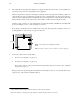
a. If the processing unit is analog video, analog audio, or digital audio, open the top cover and check that the
internal rotary voltage selection switch is set to the proper line voltage. See “Voltage Selector Switch”
on page
2–12. (The digital video and HD video processing units are auto–sensing and do not require a voltage selector
switch.)
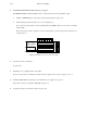
b. All processing units include a CPU DIP switch ‘S1.’ While checking voltage settings, confirm that S1 is set
with switches 1, 2, and 3 ‘ON’ and all others ‘OFF.’ See page 2–23.
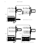
c. If the Saturn installation includes a RPP 3500 Redundant Processing Power Supply, the RPP 3500 must be
fully connected to all Processing Units and powered on in order to properly check the line voltage settings.
See page 2–14. (The HD video processing unit has its own redundant power supply.)
4. If the processing unit is digital audio, refer to “Special Instructions for Digital Audio Processors,” page 2–25.
5. If the processing unit is HD video, it must be set for the appropriate high definition standard. This can be done using
software (as described on page 3–38) or by using DIP switch S–4 (as described on page
2–24).