
Installation manual

Hardware installation2–47
AGAINST RISK OF FIRE,
TYPE AND RATING OF FUSE.
TALLY
CONFIG
P
E
T
E
XPT BUS MPK
47–63HZ
115V: 250V 1.0A SLOW BLOW
CONTINUED PROTECTION
115V: 250V 1.0A SLOW BLOW
230V: 250V T0.5A
230V: 250V T0.5A
WARNING: FOR
1A/0.5A
1A/0.5A
100/120/140/200/220/240V
100/120/140/200/220/240V
REF
ALARM
REPLACE ONLY WITH SAME
IN 8IN 1
REF
IN 0 IN 2 IN 3 IN 4 IN 5 IN 6 IN 7 IN 9 IN 10 IN 11 IN 12 IN 13 IN 14
OUTPUTS
BA
BA
BA
OUTPUTS
OUTPUTS
AES
REF IN
INPUT
SYNC
INPUT
SYNC
INPUT
SYNC
REF
LOCK
FAN
IN 15
OUTPUTS
IN 0 IN 3IN 2IN 1 IN 4 IN 7IN 6IN 5
IN 0 IN 3IN 2IN 1
IN 0 IN 3IN 2IN 1
IN 8 IN 11IN 10IN 9 IN 12 IN 15IN 14IN 13
IN 4 IN 7IN 6IN 5 IN 8 IN 11IN 10IN 9 IN 12 IN 15IN 14IN 13
IN 4 IN 7IN 6IN 5 IN 8 IN 11IN 10IN 9 IN 12 IN 15IN 14IN 13
AES MATRIX INPUTS CH 5/6
AES MATRIX INPUTS CH 3/4
AES MATRIX INPUTS CH 1/2
VIDEO MATRIX INPUTS
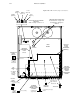
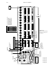
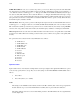
from On–Air
output of Video
Processor
Optional serial cable
connected to serial port
of Jupiter File Server.
5
MPK Serial Cable
Connected to Saturn
Control Console or CP
300/10/20/30 control
panel.
6
from On–Air CH 1/2
output of audio
processor
Emergency inputs
“Select” button group key positions
Input to main
power supply
AIR
Input to
redundant
power supply
Note: Early versions of CE 300
software will cause the button
sequence to run from the top
down rather than from left to
right. Contact Thomson for
information about updating this
software to a newer version.
Video matrix
reference input
Ferrite cores must be installed
on audio connectors to meet CE
EMI standards.
Recommended
audio sync ref.
input.
Alternate audio sync ref.,
using video signal. Note
looping cable leading to
video ref. connector.
2
Select
MSTR
IN 3
IN 0
IN 6
IN 9
IN 12
IN 1
IN 4
IN 7
IN 10
IN 13
IN 2
IN 5
IN 8
IN 11
IN 14
Transmitter
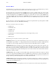
Figure 2–36.
DAB 3500/4000 Backup
Switcher, showing basic
installation.
3
4
1
See page 2–49.
2
See page 2–49.
3
See page 2–49.
4
See page 2–44.
5
See page 2–55.
6
See page 2–57.
1