
Installation manual

Hardware installation2–45
If a second or third DAP processor is used, connect the outputs of the second processor to AES matrix inputs
CH3/4 input 00. A third DAP would connect to AES matrix inputs CH5/6 IN. Connect additional sources of
your choosing to CH3/4, and CH5/6 IN 1 through 15 if applicable.
11. When an internal CE 300 Controller card is used (the usual case), connect the MPK port on the back of the DAB
to the desired control panel(s):
— If this is a single channel Saturn MCS system, this will probably be the built in “Select” button group on
the MCC 3500/4000 console.
— In a multi–channel system, the “Select” panel is used for delegation of the MCC, and other control panels
will be required to operate the Backup Switcher. A CP 300/10/20/30 (“Mars type”) control panel may be
used for this purpose.
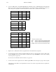
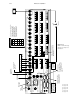
12. Set the DIP switch for the “Select” button group on the MCC as follows:
a. Lift up the console top. With power off, locate MPK (Select) panel DIP switch package S1. This is an 8–posi-
tion switch on the right–hand edge of the console.
b. If the Select button group will be used to operate the backup switcher:
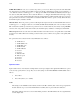
(1) Set for “CE 300 Control” (switch 8 ON). For a drawing of this switch, see page 2–52.
(2) Set the panel type for type “3” (switch 6 and 7 both ON).
(3) Set the output number (usually zero, as described in Step 2 above; in which case switches 1 through 5 are
all OFF).
c. If the Select button group will be used for delegation, set for “non–CE 300 Control” (switch 8 OFF). (If
switch 8 is OFF, all other switches are ignored.) For an illustration, see page 2–52.
d. Close the console and re–power.
13. If a CP 300/10/20/30 control panel is being used to operate the backup switcher, check the control panel DIP
switches (beneath an access cover on the rear of the panel):
a. Set for “CE 300 Control” (switch 8 ON).
b. Set the panel type:
— CP 300 and CP 330 (type “0”); switches 6 and 7 both OFF.
— CP 310 (type “1”); panel; switch 6 ON, switch 7 OFF.
— CP 320 (type “2”); switch 6 OFF, switch 7 ON.
c. Set the output number (usually zero, as described in Step 2 above; in which case switches 1 through 5 are all
OFF).
Note: if multiple 300 series panels are being used, the DIP switches must be set to a different output
number on each panel, and special software configuration methods may be needed. For more in-
formation, see Appendix E.