
Installation manual

2–44 Hardware installation
If this video reference is also used for audio sync, then video reference must also be looped through the audio “REF”
connectors (for more information, see page 2–49).
10. Connect the AIR output of each Processing Unit to the appropriate Zero input of the DAB Backup Switcher. Con-
nect the desired Emergency Backup sources to the remaining inputs. See pages 2–53 and 2–54.
a. Video Processors—amplified instructions.
If this is a digital video system, connect one of the AIR outputs of the DVP 3500/4000 to input 0 of the DBX
3500. See page 2–47. Connect additional sources of your choosing to inputs 1 through 15 of the DBX 3500.
Connect one of the outputs of the DBX 3500 to your transmitter path. The other output might be used for an
on–air monitor.
If this is an analog video system, connect one of the AIR outputs of the AVP 3500/4000 to input 0 of the ABX
3500. See page 2–47. Connect additional sources of your choosing to inputs 1 through 15 of the ABX 3500.
Connect one of the outputs of the ABX 3500 to your transmitter path. The other output might be used for an
on–air monitor.
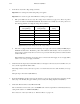
The rear panel connectors will correspond to the Select panel buttons as shown on page 2–47.
Note: Early versions of CE 300 software will cause the button sequence to run from the top down
rather than from left to right. Contact Thomson for information about updating this software to a
newer version.
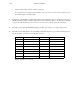
On CP 300/10/20/30 panels, the DAB rear panel connectors will correspond to the first 16 input buttons, in
sequential order.
b. Audio Processors—amplified instructions.
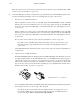
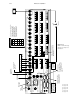
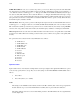
The DAB 3500/4000 Digital Audio Backup Switcher and DEX 3500 Digital Audio Mezzanine boards are
each shipped with five ferrite cores. For CE certification these cores aid in EMI reduction. Each green plug–on
terminal connector (Phoenix “Combicon” connector) should have a ferrite core clipped around the audio
cables (4 audio cables per ferrite) at the time of installation (see Figure 2–34). Ferrite cores work best when
they are near the connector. Care should be taken in handling not to drop breakable ferrite materials. For an
illustration of the Combicon connector, see page 2–76.
Figure 2–34. Ferrite core installation.
Connect the DAP ON AIR output to the DAB AES matrix inputs CH1/2 IN 0 using shielded twisted pair cable.
Connect additional sources of your choosing to IN 1 through 15.
Note: Be sure the audio sources match connectors numbers with the corresponding video sources.
For example, if VTR1 video is connected to video Input 1, then the audio from VTR1 must be con-
nected to audio Input 1.There is no provision for split switching.