
Installation manual

Hardware installation2–43
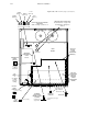
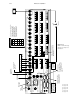
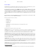
6. Set the S–1 DIP switches on the DBX 3500 Digital Video Mezanine board (or ABX 3500 Analog Video Mezanine
Board) to select the correct reference signal type (Figure 2–31) and desired switch point (Figures 2–32 and 2–33).
The switch point is adjustable in 1/2 line increments from minus 1 line to +2.5 lines from “nominal.”
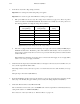
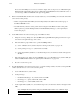
Reference signal
S1–3 S1–2 S1–1
NTSC OFF OFF OFF
PAL OFF OFF ON
Sony HDTV ON OFF OFF
EUREKA HDTV ON OFF ON
Figure 2–31. DBX 3500 reference signal settings.
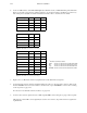
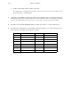
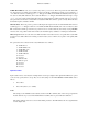
Field Select S1–5 S1–4
Field 1 only OFF ON
Field 2 only ON OFF
Either field ON ON
Don’t care OFF OFF
Figure 2–32. DBX 3500 switch point settings.
Switch Point S1–8 S1–7 S1–6
minus 1.0 line OFF OFF OFF
minus 0.5 line OFF OFF ON
Nominal
†
OFF ON OFF
+ 0.5 line OFF ON ON
+ 1.0 line ON OFF OFF
+ 1.5 line ON OFF ON
+ 2.0 line ON ON OFF
+ 2.5 line ON ON ON
Figure 2–33. DBX 3500 switch point settings.
7. Replace the cover. Mount the unit in an equipment rack near the Saturn Processing Units.
8. Connect the audio reference signal (as determined during Step 5 above) to the appropriate connectors. If the recom-
mended AES/EBU reference is used, it will be connected to the 3–pin “AES REF IN” connector. For a drawing
of the rear panel, see page 2–47.
For a discussion of alternative reference methods, see page 2–49.
9. Connect a video reference signal to the video “REF” input (the REF connector along the top edge of the rear panel).
Although any constant APL color test signal may be used for video reference, the preferred reference signal is ana-
log black burst.
†
“Nominal” is defined as follows:
NTSC 32 microseconds into line #10 either/both fields
PAL 32 microseconds into line #6 and/or line #319
Sony 16 microseconds into line #5 either/both fields
EUREKA 16 microseconds into line #5 and/or line #630