
Installation manual

2–42 Hardware installation
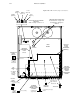
2. On the base board, check voltage settings as follows:
Important: Do not change the switch setting with power applied.
Important: Do not touch any part of the DAB interior while power is applied!
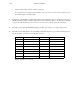
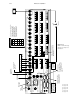
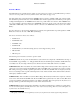
a. With power OFF, locate the two rotary line voltage selector switches (see page 2–41). These six position
switches are marked “220/100/240/120/200/140.” Both switches are normally set to the same position. Use
the following guidelines for setting the voltage selector switches:
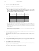
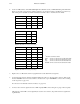
Redundant Supplies
AC input Range
Single Supply
AC Input Range
Switch Voltage
Setting
85–100 90–110 100
100–120 108–130 120
115–135 120–150 140
170–205 180–220 200
185–225 200–235 220
205–245 210–255 240
Figure 2–30. Digital audio backup switcher line voltage settings.
b. If the unit is equipped with the internal redundant power supply (the usual case) PWR_ALARM jumpers
JN200/201 should be in the “Redundant” position. This enables the alarm circuitry on the second (lower rear
panel connector) supply. If only the lower connector is powered, the unit will operate but a continuous alarm
condition will exist.
When installed, the redundant power supply is diode–connected to the main supply; in case of supply failure,
switch–over to to the good supply is automatic.
3. Check the level and output rotary hexadecimal switches S–1 through S–5. In most cases, the level will be “01” (for
video) and the output number will be “000.”
The backup switcher control system only responds to one switcher level, and video–audio breakaway is not sup-
ported.
The input range is fixed at 0–15 (000–00F hex).
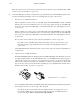
4. If an internal CE 300 Controller card is used (the usual case), remove the paper between the coin battery and the
battery clip on the CE 300. (The paper insulator preserves battery life during shipment and installation.)
5. Check audio Reference Mode rotary DIP switch S400.
The recommended source for audio sync is an AES/EBU audio reference signal. The recommended (and factory)
setting for this switch is “4–48KHZ AUTO(REC).”
\For a discussion of other sync methods, see “Reference Modes” on page 2–49.