
Installation manual
2–40 Hardware installation
Digital Audio Backup Switcher (DAB 3500/4000) hardware installation
The DAB 3500/4000 is usually controlled by a CE 300 Control Board mounted inside the DAB chassis. The CE 300 is
connected via an independent MPK bus to a control panel:
— If the Saturn system is single channel (e.g., one video processor and associated audio processors), the
backup switcher will be controlled by the “Select” button group on the Saturn control console. Please
refer to the drawing on page 2–53.
— If the Saturn system is multi–channel, the Select push buttons on the control console will not be available
(they must be used for channel selection, delegation, etc.). In this case, the backup control panel will most
often be a CP 300, 310, 320, or 330 panel. Please refer to the drawing on page 2–54.
Installation procedure
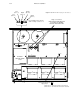
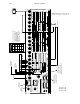
1. Base board and DEX 3500 Digital Audio Mezzanine board(s) (see Figure 2–29). With power OFF, remove the top
cover and check the following items:
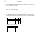
a. Input / output level setting jumpers. The 16 inputs and two outputs are individually set at the factory for 5 volt
operation.
Since these jumpers are located along the back edge of these boards, changing them will usually require the
video mezzanine board, and possibly one or two audio mezzanine board(s), to be removed. If a video mezza-
nine board is installed (the usual case), you must remove the board’s two mounting screws and the nuts on
all 20 BNC connectors. Likewise the audio mezzanine board(s) may have to be removed; each of these is fas-
tened with six nuts and five screws.
For additional information about the input and output sensitivity jumpers, see page 2–48.
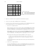
b. Check jumpers JN600 through JN604. The functions of these jumpers are as follows:
JN–600 Spare
JN–601 20/24 bit select. Factory setting is “24,” meaning that all 24 bits will be treated as data.
When “20” is selected (by removing the jumper), the first 20 bits of audio will be treated
as data and the following four bits will be passed through. For additional information,
see “Input Resolution” on page 2–50.
JN–602 Internal sine generator. Used for factory test. See page 2–51.
JN–603 Spare
JH–604 Watchdog. Used for product development.
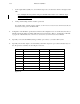
c. Check Valid Bit jumpers JN605 and 606.
With JN606 installed, the system will respond to a “data not valid” bit by muting the audio. With JN605 insta-
talled (the factory setting), the Valid Bit will be ignored. For additional information, see “V Bit Ignore/En-
able” on page 2–51.