
Installation manual

2–38 Hardware installation
c. Set the output number (usually zero, as described in Step 2 above; in which case switches 1 through 5 are all
OFF).
Note: if multiple 300 series panels are being used, the DIP switches must be set to a different output
number on each panel, and special software configuration methods may be needed. For more in-
formation, see Appendix E.
d. At this point the backup switcher should be operational.
For complete charts of settings for these switches, see CP 300 Series Control Panels / CE 300 Control Board
Installation manual, part no. 04-045227-002.
11. Configuration of the CE 300 is optional, but recommended. If a configuration set is not downloaded, the Select (or
CP 320) panel display will show numbers (000–014) instead of mnemonics. Refer to “Configuration of CE 300”
on page 2–55 of this manual, and to CP 300 Series Control Panels / CE 300 Control Board manual.
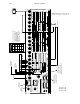
12. Optionally, connect the Alarm BNC (floating, normally open contact) to your station alarm system.
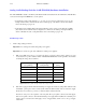
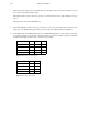
13. Optionally, wire the tally outputs to an external tally system. Each output is an opto–isolated solid state relay con-
tact. The pinout for each tally is shown in Figure 2–27 below.
Tally #
‘D’ Connector Pins Tally # ‘D’ Connector Pins
0 1, 20 8 9, 28
1 2, 21 9 10, 29
2 3, 22 10 11, 30
3 4, 23 11 12, 31
4 5, 24 12 13, 32
5 6, 25 13 14, 33
6 7, 26 14 15, 34
7 8, 27 15 16, 35
Figure 2–27.