
Installation manual

2–36 Hardware installation
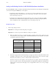
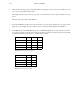
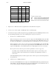
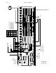
Switch Point
S8 S7 S6
minus 1.0 line OFF OFF OFF
minus 0.5 line OFF OFF ON
Nominal
†
OFF ON OFF
+ 0.5 line OFF ON ON
+ 1.0 line ON OFF OFF
+ 1.5 line ON OFF ON
+ 2.0 line ON ON OFF
+ 2.5 line ON ON ON
Figure 2–26. Settings for S6 through S8.
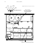
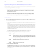
5. Replace the cover. Mount the unit in an equipment rack near the Saturn Processing Units.
6. Connect a video reference signal to the REF input. This is a terminating input.
7. Connect the Air output of each Processing Unit to the appropriate Zero input of the AAB Backup Switcher. Connect
the desired Emergency Backup sources to the remaining inputs. See pages 2–53 and 2–54.
a. Video Processors—amplified instructions.
If this is an analog video system, connect one of the Air outputs of the AVP 3500/4000 to IN 0 of the ABX
3500. Connect additional sources of your choosing to inputs 1 through 15 of the ABX 3500. Connect one of
the outputs of the ABX 3500 to your transmitter path. The other output might be used for an on–air monitor.
If this is a digital video system, connect one of the Air outputs of the DVP 3500/4000 to IN 0 of the DBX 3500.
Connect additional sources of your choosing to inputs 1 through 15 of the DBX 3500. Connect one of the
outputs of the DBX 3500 to your transmitter path. The other output might be used for an on–air monitor.
The rear panel connectors will correspond to the Select panel buttons as shown on page 2–39.
Note: Early versions of CE 300 software will cause the button sequence to run from the top down
rather than from left to right. Contact Thomson for information about updating this software to a
newer version.
On CP 300/310/320/330 panels, the AAB rear panel connectors will correspond to the first 16 input buttons,
in sequential order.
b. Audio Processors—amplified instructions.
Connect the AAP 3500/4000 left On Air output to the AAB 3500/4000 left IN 0 using shielded twisted pair
cable. Similarly, connect the AAP right On Air output to the AAB right IN 0. Connect additional sources of
your choosing to left inputs 1 through 15 and right inputs 1 through 15.
†
“Nominal” is defined as follows:
NTSC 32 microseconds into line #10 either/both fields
PAL 32 microseconds into line #6 and/or line #319
Sony 16 microseconds into line #5 either/both fields
EUREKA 16 microseconds into line #5 and/or line #630