
Installation manual

Hardware installation2–35
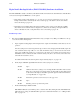
2. Check the level and output rotary hexadecimal switches S–1 through S–5. In most cases, the level will be “01” (for
video) and the output number will be “000.”
The backup switcher control system only responds to one switcher level, and video–audio breakaway is not sup-
ported.
The input range is fixed at 0–15 (000–00F hex).
3. If an internal CE 300 Controller card is used (the usual case), remove the paper between the coin battery and the
battery clip on the CE 300. (The paper insulator preserves battery life during shipment and installation.)
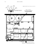
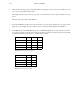
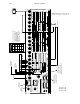
4. Set the DIP switches on the ABX 3500 (analog video) or DBX 3500 (digital video) board to select the correct refer-
ence signal type (Figure 2–24) and desired switch point (Figures 2–25 and 2–26). The switch point is adjustable
in 1/2 line increments from minus 1 line to +2.5 lines from “nominal.”
Reference signal
S3 S2 S1
NTSC OFF OFF OFF
PAL OFF OFF ON
Sony HDTV ON OFF OFF
EUREKA HDTV ON OFF ON
Figure 2–24. Settings for S1 through S3.
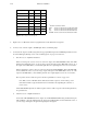
Field Select S5 S4
Field 1 only OFF ON
Field 2 only ON OFF
Either field ON ON
Don’t care OFF OFF
Figure 2–25. Settings for S4 and S5.