
Installation manual

Hardware installation2–33
Analog Audio Backup Switcher (AAB 3500/4000) hardware installation
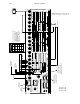
The AAB 3500/4000 is usually controlled by a CE 300 Control Board mounted inside the AAB chassis. The CE 300 is
connected via an independent MPK bus to a control panel:
— if the Saturn system is single channel (e.g., one video processor and associated audio processors), the
backup switcher will be controlled by the “Select” button group on the Saturn control console. Please
refer to the drawing on page 2–53.
— if the Saturn system is multi–channel, the Select push buttons on the control console will not be available
(they must be used for channel selection, delegation, etc.). In this case, the backup control panel will most
often be a CP 300, 310, 320, or 330 panel. Please refer to the drawing on page 2–54.
Installation procedure
1. Check voltage settings as follows:
Important: Do not change the switch setting with power applied.
Important: Do not touch any part of the AAB interior while power is applied!
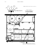
a. With power OFF, remove the top cover and locate the two rotary line voltage selector switches (see page
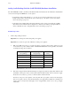
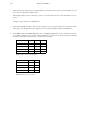
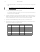
2–34). Note the six position switches marked “220/100/240/120/200/140.” Use the guidelines shown below
for setting the voltage selector switches.
Redundant Supplies
AC input Range
Single Supply
AC Input Range
Switch Voltage
Setting
80–100 85–105 100
95–120 103–125 120
115–135 120–140 140
165–205 175–215 200
180–225 190–235 220
195–245 205–255 240
Figure 2–22. Analog audio backup switcher line voltage settings.
b. If the unit is equipped with the internal redundant power supply (the usual case) jumper JN1 should be in the
“Redundant” position (pins 1 and 2 connected). This enables the alarm circuitry on the second (lower) supply.
If only the lower connector is powered, a continuous alarm condition will exist.
Note the two AC power cord receptacles on the rear panel. The top receptacle connects to the main supply;
the lower receptacle connects to the internal redundant power supply. When installed, the redundant power
supply is diode–connected to the main supply; in case of supply failure, switch–over to to the good supply
is automatic.