
Installation manual
Hardware installation2–31
As a result, even with asynchronous sources, crossfades, mixes, and other audio transitions can be made without any
audible noises or clicks when all takes are made on the preset bus and transitions made to place the signals on program.
Hot “takes” made on the program bus may have these audible switching artifacts. The rate convertors allow completely
asynchronous signals to be used on–the–air without any audible consequences except for the slightly increased distortion
due to the rate convertors themselves.
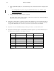
The Digital Audio Setup table (page 3–41) provides the following settings:
1. Auto rate convert. This setting uses the lock detectors on each input to determine if the signal is locked to the internal
reference. The rate convertors are used only when an incoming signal is asynchronous. This is the preferred setting.
2. Force rate convert. This setting forces full–time use of the rate convertors. This setting would be used if your plant
has a large number of asynchronous sources or if these sources are so near synchronous that the lock detectors in
the DAP cannot determine a lock condition (This might occur, for example, if a source is within 0.1 Hz of the refer-
ence long–term.) The disadvantage is that increased distortion will result on all incoming signals due to imperfec-
tions in the sample rate process.
Output Resolution
The DAP always generates 24 bit data internally. Because all internal signals are gain scaled as part of normal operation,
24 bit data will be generated regardless of the number of significant bits that are input to the DAP. The AES/EBU standard
specifies that either 20 or 24 bit sample data can be transmitted.
In addition, the DAP provides high quality dithering and rounding of the output signals to provide maximum signal per-
formance and recovery of low level information in the digital audio signals. Correct dithering and rounding of a digital
audio signal allows information to be recovered in a signal that is lower in level than the least significant bit represents.
For example, a 16 bit sampled signal can still contain information from the 18th or even the 20th bit that would be lost
with simple truncation. (For a more detailed explanation of this see the references mentioned at the end of this section)
The Digital Audio Setup table (page 3–41) allows the user to select both the number of significant bits (what the signal
is dithered and rounded to) and the number of bits sent in the AES/EBU data stream. For example, if the transmission
path is 16 bit, you might choose to use the setting that rounds and dithers to 16 bits (16 significant) but sends 20 bits in
the AES/EBU data stream. Or if the transmission path is a 20 bit, you might set the DAP to 20 bit significant, with 20
or 24 bits sent.
The dither and rounding function can also be defeated by selecting the “dither off, 20 bits sent” or “dither off, 24 bits
sent” settings.
One of the great advantages of using correct dither and rounding, is that you will deliver a quality signal to your transmis-
sion path regardless of the number of significant bits in the incoming signals to the DAP 3500. A system set to 16 bits
output resolution will still recover low level information in an 18 or 20 bit incoming signal as well as lowering distortion
for all incoming signals.
Note: For best performance and minimum distortion to your end user, you should determine the number
of significant bits in your transmission path to your customer and set the DAP to match. This will allow
you to deliver the best possible quality digital audio signal to your end user.