
Installation manual
Hardware installation2–29
To use configuration software, set internal DIP switch to position “F”.
Reference Delay/Advance Adjustment
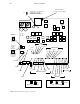
Two rotary DIP switches (see page 2–21) are provided that allow the user to move the AES/EBU frame relationship of
the DAP outputs with respect to the AES/EBU reference inputs. Normally the AES11 synchronization standard requires
that all outputs be within 5% of the reference input. When both DIP switches are set to the “0” position, the AES/EBU
frames will be essentially identical in timing with the reference input. Changing the DIP switches allows the user to make
the AES/EBU outputs either advance or delay from the reference input in 1/4 bit increments.
In normal use, these adjustments are not needed. In fact, the user could actually cause the DAP to violate the AES11
synchronization standard by introducing excessive delay.
Note: This reference delay adjustment can only be made from the internal rotary DIP switches and can-
not be applied from the configuration menus on the file server. Make adjustments here only if absolutely
needed. Normal operations will not need these adjustments.
Input Resolution
Input resolution refers to how many bits of sample data are used in processing the audio signals. The AES/EBU standard
allows for two basic operations. Standard 20 bit samples or 24 bit samples using the auxiliary data bits. The DAP can
automatically sense which is in use based upon a status bit sent along in the AES/EBU bit stream. Unfortunately many
manufacturers do not correctly set this bit. As a result, two additional options are available so the user may specify which
to accept. The DAP can be set to always use all 24 bits or to use only the most significant 20 bits. The Digital Audio Setup
table (page 3–41) provides the following settings:
1. 24 bit auto
2. Force 20 bit
3. Force 24 bit
24 Bit Auto
This setting allows each input section of the DAP to pass either 20 or 24 bits of sample based upon bit x of byte
x of the AES/EBU status block. When the bit indicates 20 bit data, whether or not the type of the four bits of auxiliary
data is specified, the DAP input stages will substitute “0s” for the bottom four LSBs (least significant bits). The
resulting 20 bit word is then passed onto the digital signal processing stages for mixing and fading. When the AES/
EBU status bit indicates 24 bit data, all 24 bits of the input sample data will be passed.
Force 20 Bit
This setting automatically truncates any auxiliary data bits by substituting “0s” for them before any digital signal
processing occurs. If any data or intercom type signals are present in these bits, they will be truncated. In addition,
if 24 bit significant data is presented, the four LSBs will be lost. This may result in increased distortion due to trunca-
tion instead of correct rounding and dithering.
This setting should be used when it is known that all data presented to the DAP will have 20 or less significant bits
of audio sample data.