
Installation manual
Hardware installation2–25
Special Installation Instructions for Digital Audio Processors
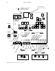
Input Sensitivity Jumpers
These jumpers are provided on the DAP 3500/4000 main board and the DAX 3500 optional matrix.
The DAP 3500/4000 is designed to receive standard AES/EBU twisted pair signals with 110 ohm impedances. The unit
is shipped from the factory with these settings. In addition, input jumpers are provided that allow signals of different
levels to be accommodated. These jumpers do not change the input impedance of 110 ohms. They only provide for differ-
ent input signals levels that may come from other versions of the AES/EBU standard. The input jumpers are required
in order to allow the adaptive equalizers that follow to properly compensate for input cable losses.
Each input section of the DAP has three jumpers: 5 V, 1 V, and CON, representing 5 volt P–P, 1 volt P–P, and CONsumer
reference levels (see page 2–21). These jumpers refer to the sending end or the equipment driving the DAP inputs. Stan-
dard AES/EBU devices should use the 5 V position.
Devices running on 75 ohm coax generally conform to SMPTE proposed standard SMPTE 276M which calls for 1V
P–P signals. Placing the jumper in the 1V position provides correct interface for the 75 ohm coax levels only. A matching
transformer with a ratio of 1:1.2 is required to provide proper impedance matching.
Many consumer devices such as CD players or DAT machines provide direct digital outputs conforming to the SPDIF
standard. The DAP can accept inputs from these signals by using the CON jumper setting. The SPDIF standard calls for
signal levels of 0.5 V P–P and an impedance of 75 ohms. A matching transformer with a ratio of 1:1.2 is required to pro-
vide proper impedance matching.
The input decoders of the DAP will decode a SPDIF type signal but will not recover any of the channel status bits as
they differ greatly from a standard AES/EBU coded signal.
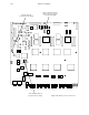
Output Sensitivity Jumpers (On All AES/EBU Outputs on Main Board)
As above, the AES/EBU output drivers have jumpers that allow the DAP to drive different signal levels. These jumpers
do not change the output impedance of 110 ohms. They only provide for different output signals levels that may be re-
quired.
Each output section of the DAP has two jumpers: 5 V and 1 V, representing 5 volt P–P and 1 volt P–P reference levels
(see page 2–21). These jumpers refer to output signal levels from the DAP outputs. Standard AES/EBU devices should
use the 5 V position. The factory ships the units set for the standard AES/EBU level of 5 volts P–P.
Devices running on 75 ohm coax generally conform to SMPTE proposed standard SMPTE 276M which calls for 1 V
P–P signals. Placing the jumper in the 1 V position provides correct interface for the 75 ohm coax levels only. A matching
transformer with a ratio of 1.2:1 is required to provide proper impedance matching to the 110 ohm output impedance
of the DAP.