
Installation manual

Hardware installation2–15
Note 6: Connect the RPP“GND” (Digital Ground) terminal to the DAP “DGND” connection. If
you want the alarm circuit to check for the presence of RPP voltage, move the DAP alarm LED
jumper JN1 to the Redundant position (pin 2 connected to pin 3—see page 2–21 for typical jumper
labelling).
3. Open the MCC 3500/4000 Control Console. On the power distribution printed circuit board, check alarm LED
jumpers JN1 and JN2; both should be in the Redundant position (pin 2 connected to pin 3).
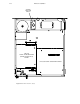
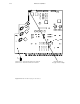
4. Remove the RPP 3500/4000 top cover and locate the rotary line voltage selector switch. This six–position switch
is marked “220 / 100 / 240 / 120 / 200 / 140.” Use the following rules to establish an initial setting:
Important: Do not change the rotary line voltage selector switch with power applied. Doing so will damage
the unit.
Important: Do not touch any part of the RPP interior while power is applied!
a. Measure the power line voltage that will be feeding your system.
b. Estimate the load level of your system. For example, one AVP plus one AAP is considered to be a “lightly
loaded” system. On the other hand, one AVP, one DVP, and three DAPs would be a “fully loaded” system.
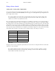
c. For a lightly loaded system, use Column B of Table 2–12. Find the number that is less than, and closest to,
the power line voltage. Look in Column A to find the initial setting and for the rotary switch and set the switch
accordingly.
Column A
Column B Column C Column D
Voltage selector switch
setting
Lowest voltage supported
(lightly loaded)
Lowest voltage supported
(fully loaded)
Highest voltage supported
(no load)
100 85 90 104
120 100 108 126
140 115 125 147
200 170 180 209
220 195 210 230
240 215 230 252
Table 2–12. RPP 3500/4000 initial voltage settings.
d. For a fully loaded system, use column C of Table 2–12. Find the number that is less than, and closest to, the
power line voltage. Look in Column A to find the initial setting for the rotary switch and set the switch accord-
ingly.
5. Apply power to the RPP. Make sure all Processing units are now being powered entirely by the RPP.
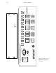
6. Observe the row of voltage LEDs on the rear panel of the RPP. Allow 5–10 seconds for the monitoring circuitry
to stabilize. All LEDs should now be green. If so, remove power and replace the top cover.