
Installation manual
2–14 Hardware installation
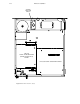
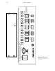
Redundant Processing Power Supply (RPP 3500/4000)
Please refer to the drawing on page 2–17.
If the system includes an RPP 3500/4000 Redundant Processing Power Supply, the RPP must be fully connected to all
Processing Units and powered on in order to properly check the line voltage settings. Proceed as follows:
1. Remove power.
2. Using 16 gauge wire (untinned), connect the RPP to the Processing Units.
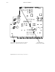
a. AVP 3500/4000 Analog Video Processing Unit—see page 2–73 for an illustration of the AVP 3500/4000 rear
panel connections and labelling.
Note 1: Connect the RPP “AGND” (Analog Ground) terminal to the right–hand AVP “GND” con-
nection. Connect the RPP “GND” terminal to the left–hand AVP “GND” connection. If you want
the alarm circuit to check for the presence of RPP voltage, move the AVP alarm LED jumper JN1
to the Redundant position (pin 2 connected to pin 3—see page 2–18 for jumper labelling).
Note 2: For AVP units only, the RPP 3500 power cables must be threaded through a ferrite bead
in order for the unit to comply with current EMI standards. The ferrite bead (part no.
29–002052–15) is supplied with the Saturn system. The bead should be located as close to the pro-
cessing unit as possible and the power wires passed through it twice.
b. AAP 3500/4000 Analog Audio Processing Unit—see page 2a–1 for an illustration of the AAP rear panel con-
nections and labelling.
Note 3: Connect the RPP “GND” terminal to the AAP “DGND” connection. Using a separate wire,
connect the RPP “AGND” to the AAP “AGND” connection. If you want the alarm circuit to check
for the presence of RPP voltage, move the AAP alarm LED jumper JN1 to the Redundant position
(pin 2 connected to pin 3—see page 2–19 for jumper labelling).
c. DVP 3500A/4000 Digital Video Processing Unit—see page 2–74 for an illustration of the DVP rear panel
connections and labelling. The DVP uses an XLR connector.
Note 4: An inset in the illustration shows the barrier–strip connector used on the earlier DVP
3500. For this model, connect the RPP terminal marked “DVP 3500 minus 21 V” to one of the DVP
3500 terminals marked “minus 40–60 V.” Connect the RPP terminal marked “DVP 3500 plus 21
V” to one of the DVP 3500 terminals marked “plus 40–60 V.” Do not connect the RPP terminal
marked “AGND.”
Note 5: If you want the alarm circuit to check for the presence of RPP voltage, move the DVP alarm
LED jumper JN1 to the Redundant position (pin 2 connected to pin 3—see page 2–20 for jumper
labelling.)
d. DAP 3500/4000 Digital Audio Processing Unit—see page 2a–5 for an illustration of the DAP rear panel con-
nections and labelling.