
Installation manual
Hardware installation2–11
15. Connect the MPK cables.
a. MPK connection to the control console’s Select button group will depend on whether the buttons are used for
delegation or to operate a Saturn Backup Switcher (AAB 3500/4000). If the Select button group will be used
for system selection (delegation), connect the console’s MPK line to the video processor (see page 2–7). If
there is a backup switcher, please refer to “Backup Switcher (AAB 3500/4000) Hardware Installation” on
page 2–33.
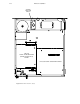
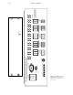
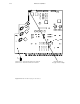
b. Install MI 3040 General Purpose/Tally Interface, if one has been supplied. The MI 3040 can be connected
to the MPK port of a Video Processing Unit (Figure 2–1) or to a VM/SI 3000 (Figure 2–4).
For details concerning hardware connection of machines to the MI 3040, refer to “Connection to Parallel–
Control Machines Using MI 3040” in Section 2 of the Jupiter Installation and Operating Manual.
Thomson offers several tally systems, including Jupiter Tally, Saturn Tally, and Andromeda. Details concern-
ing the Saturn Tally system can be found on page 2–80 of this manual.
MI 3040 software configuration varies greatly depending on the application. Discussion of configuration be-
gins in Section 3 of this manual.
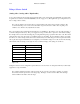
c. Thomson Under Monitor Displays (SD 3x or RP 1/2/3) can be used to indicate status of the Preview, Pro-
gram, and Air outputs (as shown on page 2–2). They are also connected to an MPK bus, but the bus source
must be a VM 3000 or SI 3000. The UMDs will display mnemonics for all inputs—whether the input is con-
nected to an internal matrix or to an external (e.g., Venus) matrix. In this application RP 1/2/3 tally lights are
not used.
UMDs should be configured to operate under “Saturn Control” (as opposed to Jupiter Control). For more in-
formation, see page 3–45.
d. For MPK cable pinouts, see page 2–67.
16. Power up the system.
a. The power switches for the Processing Units are located on the rear panels.
b. The console may be equipped with one power supply or two power supplies operating in redundant mode.
The power switches for these supplies are inside the console, in the rear, on top of the AC input connector
shields.
c. The file server should automatically download to the Saturn system, after which the “Alarm” LEDs on the
Processing Units should go from red to green.
17. Configure the system using the file server (as described in Section 3). For operating procedures, see Section 4.
18. For information about the DVE option, see page 2–86.
19. Thomson or third–party automation systems should be connected only after the Saturn system is operational. See
page 2–87.