
Installation manual

2–10 Hardware installation
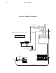
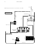
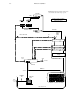
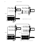
10. Install MCM 3500/4000 External Meter Bridges (if supplied).
Each MCM 3500/4000 should be installed and set to monitor the audio levels of a particular system.
a. Cabling—all MCM 3500s are connected to the audio metering bus. See page 2–68.
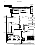
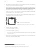
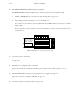
b. Switch settings (beneath rear panel access cover). See Figure 2–9.
Note 1: The rear–panel switch is wired in parallel with internal DIP switch S1; S1 is factory set with all
switches OFF.
Note 2: To monitor system 1, switches 1–4 are set to binary zero; to monitor system 2, the switches are set
to binary one, etc.
12345678
0
0
0
0
MONITOR SYSTEM NUMBER
1
0
0
0
0
1
0
0
1
1
0
0
0
0
1
0
1
0
1
0
0
1
1
0
1
1
1
0
NOT USED
NOT USED
0
10
1
PPM ONLY
PPM/VU SELECT-
ABLE VIA FRONT
PANEL SWITCH
ALWAYS SET TO 1
1
2
3
4
5
6
8
7
Figure 2–9. MCM 3500 rear panel DIP switch settings.
11. Connect the system control LAN.
See page 2–63.
12. Install file server (configuration PC) on the LAN.
In most cases, the file server will be the same PC used for a Jupiter control system. See page 2–4 or 2–3.
13. Install the VM/SI 3000 Control Systems on the LAN, if they are supplied. See page 2–4.
Stand–alone systems do not include a VM 3000. See page 2–3.
14. Connect the required sync reference cables. See page 2–70.