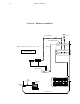
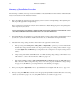
2–1 Hardware installation Section 2 – Hardware Installation Video and Audio Transmitter 16 T Internal Matrix option Video Processing Unit Figure 2–1. Basic Saturn Stand–alone system. MPK bus T Refer to text for complete wiring instructions.
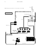
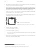
–2 Hardware installation Transmitter Figure 2–2. Expanded Saturn Stand–alone system with Saturn–controlled UMDs Video and Audio T Refer to text for complete wiring instructions.
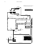
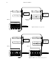
2–3 Hardware installation Figure 2–3. Expanded Saturn Stand–alone system with tally and backup options. MI 3040 Tally Refer to text for complete wiring instructions.
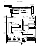
2–4 Hardware installation Crosspoint Bus router Refer to text for complete wiring instructions.
2–5 Hardware installation Summary of Installation Procedure The following is a summary of the steps needed for installation of the Saturn Master Control Switcher. Additional details may be found elsewhere in this manual as indicated. 1. Before unpacking the equipment, inspect the shipping carton for evidence of freight damage. After unpacking carefully inspect all equipment for freight damage. If the contents have been damaged, notify the carrier and Thomson.
2–6 6. Hardware installation The switcher Processing Units (and redundant power supply) should be mounted in a rack or other suitable enclosure that provides power and cooling facilities for the equipment. The Processing Units are designed for mounting in a standard 19–inch wide equipment rack having a depth of 24 –30 inches. Rear support is recommended, especially in a remote equipment truck or in other locations subject to vibration and stress.
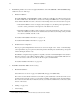
2–7 Hardware installation Video Video System (Channel) A Audio Channels 1/2 Audio Channels 1/2 System (Channel) B Audio Channels 3/4 MPK bus Multiple audio channels ÎÎ ÎÎ Î Î Î ÎÎ Î Î ÎÎ Î ÎÎ Î ÎÎ Î ÎÎÎÎÎÎÎ ÎÎ ÎÎÎ ÎÎ ÎÎÎ ÎÎ Î ÎÎ ÎÎ ÎÎÎÎÎÎÎÎ ÎÎ ÎÎÎ ÎÎÎ ÎÎÎ ÎÎ “SATCON” Figure 2–6. Multi–system application.
2–8 8. Hardware installation Install Backup Switcher, if one has been supplied. Installation of the AAB 3500/4000 or DAB 3500/4000 backup switcher involves two main steps: a. Hardware installation. The AAB 3500/4000 or DAB 3500/4000 is usually controlled by a CE 300 Control Board mounted inside the AAB or DAB chassis. The CE 300 is connected via an independent MPK* bus to a control panel. The chassis with the CE 300A card can be connected to another backup chassis and connected with a crosspoint.
2–9 Hardware installation If the “Select” button group will be used for system selection (delegation): (1) Lift up the console top (see Figure 2–8). With power off, locate MPK (Select) panel DIP switch package S1. This is an 8–position switch on the right–hand edge of the console. (2) Set for “non–CE 300/SC 400 Control” (switch 8 OFF). (If switch 8 is OFF, all other switches are ignored.) See Figure 2–37 on page 2–52.
2–10 10. Hardware installation Install MCM 3500/4000 External Meter Bridges (if supplied). Each MCM 3500/4000 should be installed and set to monitor the audio levels of a particular system. a. Cabling—all MCM 3500s are connected to the audio metering bus. See page 2–68. b. Switch settings (beneath rear panel access cover). See Figure 2–9. Note 1: The rear–panel switch is wired in parallel with internal DIP switch S1; S1 is factory set with all switches OFF.
2–11 15. Hardware installation Connect the MPK cables. a. MPK connection to the control console’s Select button group will depend on whether the buttons are used for delegation or to operate a Saturn Backup Switcher (AAB 3500/4000). If the Select button group will be used for system selection (delegation), connect the console’s MPK line to the video processor (see page 2–7). If there is a backup switcher, please refer to “Backup Switcher (AAB 3500/4000) Hardware Installation” on page 2–33. b.
2–12 Hardware installation Voltage Selector Switch (Analog video / analog audio / digital audio) A six–position switch is located near the front panel of the analog video, analog audio, and digital audio processing units. A typical selector switch (for the DAP 3500/4000) is shown on page 2–13. (The digital video processing unit does not have a voltage selector switch.) Note 1: Power must be removed from the processing unit before the voltage selector switch is changed.
2–13 Hardware installation VOLTAGE SELECTOR SWITCH DMX 3500 DIGITAL AUDIO CONVERTER (ANALOG AUDIO OUTPUT) OPTION DAX 3500A DIGITAL AUDIO MATRIX OPTION Figure 2–11. DAP 3500/4000 chassis.
2–14 Hardware installation Redundant Processing Power Supply (RPP 3500/4000) Please refer to the drawing on page 2–17. If the system includes an RPP 3500/4000 Redundant Processing Power Supply, the RPP must be fully connected to all Processing Units and powered on in order to properly check the line voltage settings. Proceed as follows: 1. Remove power. 2. Using 16 gauge wire (untinned), connect the RPP to the Processing Units. a.
2–15 Hardware installation Note 6: Connect the RPP“GND” (Digital Ground) terminal to the DAP “DGND” connection. If you want the alarm circuit to check for the presence of RPP voltage, move the DAP alarm LED jumper JN1 to the Redundant position (pin 2 connected to pin 3—see page 2–21 for typical jumper labelling). 3. Open the MCC 3500/4000 Control Console.
2–16 Hardware installation The voltage LEDs (marked +8 V, –11 V, +11 V, –21 V, and +21 V) can be green, red, or orange. Green means the input line voltage is adjusted properly for that output. Red means the input line voltage is too low for that output, so the rotary line voltage selector switch needs to be lowered. Orange means the input line voltage is too high for that output, so the rotary line voltage selector switch needs to be increased. 7. a.
O I POWER PE –21V TE 47–63HZ 100/120/200/220/240V 10/5A ALARM SEE INSTALLATION INSTRUCTIONS BEFORE CONNECTING TO THE SUPPLY. VOIR LA NOTICE D INSTALLATION AVANT DE RACCORDER AU RESEAU. VOR DER INBETRIEBNAHME INSTALLATIONSHINWEISE BEACHTEN. 3A 3A AVP–3500 3A 3A 3A 3A 3A 3A AAP–3500/DAP–3500 3A POWER/ALARM 3A 3A 3A 3A DVP–3500 3A FOR CONTINUED PROTECTION AGAINST RISK OF FIRE, REPLACE ONLY WITH SAME TYPE AND RATING OF FUSE.
2–18 Hardware installation JN 1401 1 2 3 JUMPER PINS 1–2 = NO REDUNDANT POWER SUPPLY INSTALLED JUMPER PINS 2–3 = REDUNDANT POWER SUPPLY INSTALLED Figure 2–14. AVP 3500/4000 jumpers and switches. CPU DIP switch S1.
2–19 Hardware installation JN 1 1 2 3 JUMPER PINS 1–2 = NO REDUNDANT POWER SUPPLY INSTALLED JUMPER PINS 2–3 = REDUNDANT POWER SUPPLY INSTALLED Figure 2–15. AAP 3500/4000 jumpers and switches. CPU DIP switch S1.
2–20 Hardware installation JN 1 3 2 1 JUMPER PINS 1–2 = NO REDUNDANT POWER SUPPLY INSTALLED JUMPER PINS 2–3 = REDUNDANT POWER SUPPLY INSTALLED Figure 2–16. DVP 3500/4000 jumpers and switches. CPU DIP switch S1.
2–21 Hardware installation JN 1 CPU DIP switch S1. See page 2–23 for settings JUMPER PINS 1–2 = NO REDUNDANT POWER SUPPLY INSTALLED JUMPER PINS 2–3 = REDUNDANT POWER SUPPLY INSTALLED 1 2 3 REFERENCE MODE FACTORY SETTING = F METER SEL FACTORY SETTING = 0 (BOTH SWITCHES) PST PGM OFF AIR MONITOR INPUTS MON B MON A EXT 2 EXT 1 OFF AIR EXT 3 CH 5/6 CH 3/4 SPARE DELAY OFFSET ADJUSTMENT See page 2–29 for discussion. 11.2850 CAL 12.288 CAL IN 17 AES OUT ON AIR PGM 6.
2–22 Hardware installation CPU DIP switch S1. See page 2–23 for settings Video Standard switch S4. See page 2–24 for settings.. Xilinx configuration switches (factory use only). See page 2–21 for default settings Figure 2–18. HDVP 3500/4000 DIP switches.
2–23 Hardware installation Operational DIP Switch (S1) Settings The CPU DIP switch S1 is normally used for factory test and setup only. Normal operation is for switch positions 1, 2, and 3 to be ‘ON’ with all other positions ‘OFF.’ 1 0 Watchdog reset enable (default) Watchdog off Version 1.xx software (psos) 1 0 Version 2.
2–24 Hardware installation HDVP Video Standard DIP Switch (S4) Settings S4 is always effective when S14–6 is ON (as shown in Figure 2–21). It may or may not be effective when S14–6 is OFF, depending on a table setting (as described on page 3–38). Leave OFF Divide frame/field rate by 1.001 Do NOT divide frame/field rate by 1.001 0 1 0 0 0 0 1 1 1 0 1 0 1 1 0 0 0 1 0 0 0 0 1 0 0 0 0 1 0 1080i 60, 16x9, SMPTE 274M, ATSC Table 3 @ 1.5 Gb/s 1035i 60, 16x9, SMPTE 260M @ 1.
2–25 Hardware installation Special Installation Instructions for Digital Audio Processors Input Sensitivity Jumpers These jumpers are provided on the DAP 3500/4000 main board and the DAX 3500 optional matrix. The DAP 3500/4000 is designed to receive standard AES/EBU twisted pair signals with 110 ohm impedances. The unit is shipped from the factory with these settings. In addition, input jumpers are provided that allow signals of different levels to be accommodated.
2–26 Hardware installation Reference Modes The DAP must have an external reference signal to provide synchronous operation. The DAP can operate in many different modes. Normally these modes are selected from the Jupiter file server as part of configuration. However for convenience of factory test procedures, a 16 position rotary DIP switch is provided to select these modes (see page 2–21). The very same selections are provided in the configuration software that are available using this DIP switch.
2–27 Hardware installation 2. 48 kHz NTSC Video. This mode utilizes a local video PLL locking to Horizontal sync which is then compared to a divided down version of the internal 12.288 MHz clock. The 12.288 MHz clock is generated by a low–jitter secondary PLL which provides approximately equivalent performance to the AES low–jitter PLL.
2–28 Hardware installation All VU and PPM meter outputs require frequency information for the filtering functions. This information is obtained from the reference section of the DAP. If operating at frequencies other than + or – 4% of 32 kHz, 44.1 kHz, or 48 kHz, the meters will show incorrect ballistics. 10. AES vari speed. This mode is the same as the AES Automatic mode mentioned above except that the low–jitter PLL circuits are never enabled.
2–29 Hardware installation To use configuration software, set internal DIP switch to position “F”. Reference Delay/Advance Adjustment Two rotary DIP switches (see page 2–21) are provided that allow the user to move the AES/EBU frame relationship of the DAP outputs with respect to the AES/EBU reference inputs. Normally the AES11 synchronization standard requires that all outputs be within 5% of the reference input.
2–30 Hardware installation Note: The DAP does not pass auxiliary data bits separately under any condition. If these bits are being used in your facility for intercom or other data the “Force 20 bit” mode should be used to prevent any data or noise in the auxiliary bits from causing increased distortion or noise in the main audio channel. Force 24 Bit This setting forces all 24 bits of input sample data to be passed to the digital signal processing stages that follow.
2–31 Hardware installation As a result, even with asynchronous sources, crossfades, mixes, and other audio transitions can be made without any audible noises or clicks when all takes are made on the preset bus and transitions made to place the signals on program. Hot “takes” made on the program bus may have these audible switching artifacts.
2–32 Hardware installation DMX 3500 Digital to Analog Converter Analog Meter Output Gain When a DMX 3500 D to A convertor board is installed, the Analog Left/Right Meter Outputs of the DAP 3500/4000 can be used to drive analog meter circuitry such as a mechanical VU meter or equivalent. (A drawing of the DAP rear panel is shown on page 2a–5). These meter outputs use a simple consumer quality D to A convertor and are not intended for monitoring signal quality.
2–33 Hardware installation Analog Audio Backup Switcher (AAB 3500/4000) hardware installation The AAB 3500/4000 is usually controlled by a CE 300 Control Board mounted inside the AAB chassis. The CE 300 is connected via an independent MPK bus to a control panel: — if the Saturn system is single channel (e.g., one video processor and associated audio processors), the backup switcher will be controlled by the “Select” button group on the Saturn control console. Please refer to the drawing on page 2–53.
2–34 Hardware installation Level (bits 1–4) Level (bits 5–7) Output Output (bits 4–7) (bits 8–9) Figure 2–23. AAB 3500/4000 jumpers and switches. Output (bits 0–3) Voltage select switches Level and Output rotary switches.
2–35 2. Hardware installation Check the level and output rotary hexadecimal switches S–1 through S–5. In most cases, the level will be “01” (for video) and the output number will be “000.” The backup switcher control system only responds to one switcher level, and video–audio breakaway is not supported. The input range is fixed at 0–15 (000–00F hex). 3. If an internal CE 300 Controller card is used (the usual case), remove the paper between the coin battery and the battery clip on the CE 300.
2–36 Hardware installation Switch Point S8 S7 S6 minus 1.0 line OFF OFF OFF minus 0.5 line OFF OFF ON Nominal† OFF ON OFF + 0.5 line OFF ON ON + 1.0 line ON OFF OFF + 1.5 line ON OFF ON + 2.0 line ON ON OFF + 2.
2–37 Hardware installation Note: Be sure the audio sources match connectors numbers with the corresponding video sources. For example, if VTR1 video is connected to video IN 1, then the audio from VTR1 must be connected to audio IN 1.There is no provision for split switching. If a second or third AAP processor is used, connect the left and right outputs of the second processor to CH3 IN 0 and CH4 IN 0. A third AAP would connect to CH5 IN 0 and CH6 IN 0.
2–38 Hardware installation c. Set the output number (usually zero, as described in Step 2 above; in which case switches 1 through 5 are all OFF). Note: if multiple 300 series panels are being used, the DIP switches must be set to a different output number on each panel, and special software configuration methods may be needed. For more information, see Appendix E. d. At this point the backup switcher should be operational.
1.0A SLOW BLOW T0.
2–40 Hardware installation Digital Audio Backup Switcher (DAB 3500/4000) hardware installation The DAB 3500/4000 is usually controlled by a CE 300 Control Board mounted inside the DAB chassis. The CE 300 is connected via an independent MPK bus to a control panel: — If the Saturn system is single channel (e.g., one video processor and associated audio processors), the backup switcher will be controlled by the “Select” button group on the Saturn control console. Please refer to the drawing on page 2–53.
2–41 Hardware installation Output (bits 4–7) Output (bits 8–9) Output (bits 0–3) Figure 2–29. DAB 3500/4000 jumpers and switches.
2–42 2. Hardware installation On the base board, check voltage settings as follows: Important: Do not change the switch setting with power applied. Important: Do not touch any part of the DAB interior while power is applied! a. With power OFF, locate the two rotary line voltage selector switches (see page 2–41). These six position switches are marked “220/100/240/120/200/140.” Both switches are normally set to the same position.
2–43 6. Hardware installation Set the S–1 DIP switches on the DBX 3500 Digital Video Mezanine board (or ABX 3500 Analog Video Mezanine Board) to select the correct reference signal type (Figure 2–31) and desired switch point (Figures 2–32 and 2–33). The switch point is adjustable in 1/2 line increments from minus 1 line to +2.5 lines from “nominal.” Reference signal S1–3 S1–2 S1–1 NTSC OFF OFF OFF PAL OFF OFF ON Sony HDTV ON OFF OFF EUREKA HDTV ON OFF ON Figure 2–31.
2–44 Hardware installation If this video reference is also used for audio sync, then video reference must also be looped through the audio “REF” connectors (for more information, see page 2–49). 10. Connect the AIR output of each Processing Unit to the appropriate Zero input of the DAB Backup Switcher. Connect the desired Emergency Backup sources to the remaining inputs. See pages 2–53 and 2–54. a. Video Processors—amplified instructions.
2–45 Hardware installation If a second or third DAP processor is used, connect the outputs of the second processor to AES matrix inputs CH3/4 input 00. A third DAP would connect to AES matrix inputs CH5/6 IN. Connect additional sources of your choosing to CH3/4, and CH5/6 IN 1 through 15 if applicable. 11.
2–46 Hardware installation d. At this point the backup switcher should be operational. For complete charts of settings for these switches, see the CP 300 Series Control Panels / CE 300 Control Board manual, part no. 04-045227-002. 14. Configuration of the CE 300 is optional, but recommended. If a configuration set is not downloaded, the Select (or CP 320) panel display will show numbers (000–014) instead of mnemonics.
1.0A SLOW BLOW T0.5A 47–63HZ 1A/0.5A XPT BUS TALLY MPK Optional serial cable connected to serial port of Jupiter File Server. 5 CONFIG 1.0A SLOW BLOW T0.5A 100/120/140/200/220/240V Alternate audio sync ref., using video signal. Note looping cable leading to video ref. connector. 2 P E T E 115V: 250V 230V: 250V ALARM REF IN 1 AES REF IN IN 3 Recommended audio sync ref. input.
2–48 Hardware installation ADDITIONAL INFORMATION FOR DIGITAL AUDIO BACKUP SWITCHERS Input sensitivity Jumpers These jumpers are provided on the DAB 3500/4000 base board and the optional DEX 3500 matrix board(s). The DAB 3500/4000 is designed to receive standard AES/EBU twisted pair signals with 110 ohm impedances. The unit is shipped from the factory with these settings. In addition, input jumpers are provided that allow signals of different levels to be accommodated.
2–49 Hardware installation Reference Modes The DAB must have an external reference signal to provide synchronous operation. A rotary DIP switch is provided to select one of seven possible sync modes (for the location of this switch, see page 2–41). The audio matrix can be synchronized using an AES/EBU reference signal, or, an NTSC or PAL video reference signal.
2–50 Hardware installation 48 kHz AES AUTO. This is the factory default setting and the preferred mode. This mode provides the same ultra stable low–jitter reference at a sample rate of 48 kHz as selection #1, but has a much larger lock range of approximately + or – 4%. When the reference is within approx. + or – 200 ppm of 48 kHz, then the DAB automatically selects the super low–jitter secondary PLL.
2–51 Hardware installation 24 bit (factory set – default) This setting, which is the default, passes all 24 bits of input sample data to the digital signal processing stages that follow. This setting should be used when all data presented to the DAB has between 16 and 24 bits of significant information and there are no auxiliary data or intercom channels used in the AES/EBU bit stream.
2–52 Hardware installation 1 1 2 3 4 5 6 7 8 0 –––––OPEN––––– Output to be controlled: Standard setting 1 CE 300/SC–400 control 0 non CE 300/SC–400 control Backup setting Delegation setting Equivalent polling name: 0 0 0 0 0 0 1 1 60 1 1 0 0 0 0 1 1 61 2 0 1 0 0 0 1 1 62 3 1 1 0 0 0 1 1 63 4 0 0 1 0 0 1 1 64 5 1 0 1 0 0 1 1 65 6 0 1 1 0 0 1 1 66 7 1 1 1 0 0 1 1 67 8 9 10 11 12 13 14 15 0 1 0 1 0 1 0 1 0 0 1 1 0 0 1 1 0 0 0 0 1 1 1 1 1 1 1 1 1 1 1 1 0 0 0 0 0 0 0 0
2–53 Hardware installation Distribution switcher Video and Audio.See pages 2–71 and 2–76 for details Audio Processing Unit On Air Outputs Audio Processing Unit On Air Output Video Processing Unit Emergency inputs Sync reference For AAB wiring details see page 2–39. For DAB wiring details see page 2–36. 0 Download cable required only if mnemonics are desired; see page 2–55. For cable details, see page 2–57.
2–54 Hardware installation Distribution switcher To additional systems Video and Audio.See pages 2–71 and 2–76 for details Audio Processing Unit On Air Outputs Audio Processing Unit On Air Output Video Processing Unit Emergency inputs Sync reference Download cable required only if mnemonics are desired; see page 2–55. For cable details, see page 2–57. For AAB wiring details see page 2–39. For DAB wiring details see page 2–36.
2–55 Hardware installation Configuration of CE 300 This step is required if alphanumeric mnemonics are desired for display on the “Select” button group or on a CP 320 backup control panel. If this step is not performed, the AAB/DAB 3500/4000 Backup Switcher will still operate but the backup control panel window will display numerics only. The CE 300 is configured using an editor that is completely outside the normal Saturn/Jupiter menu structure.
2–56 Hardware installation i. The Panel Assignments tables will normally be left blank (i.e., so that the panel will control the output assigned via the panel’s DIP switch). However, if for some reason one of these tables needs to be used (to override the DIP switch setting), please note that the CP 300/330 table will be used by the Select button group; in which case “Poll 0” on this table will actually correspond to Polling Number 60, “Poll 1” will correspond to Polling Number 61, etc.
2–57 Hardware installation to AAB–3500/4000 Configuration Port 1 LG to AT–type Computer Serial Port 1 Shield 6 CD 6 G DSR 2 2 Rx Rx 7 7 3 3 Tx 8 8 Tx CTS 4 4 G DTR 9 9 G RI 5 5 LG P1 DB9P (male) Rx Receive Tx Transmit 4–6–9 Jumpered together; internally grounded 50 ft ( 15.
2–58 Hardware installation To PC–type computer serial port To AAB 3500/4000 or DAB 3500/4000 Configuration Port 1 LG 6 G 14 2 Rx 7 1 Shield 2 Orange/white Tx 15 3 3 Rx 8 16 Blue/white Tx 4 4 G 9 G 17 5 5 CTS 18 6 DSR 19 DB9P (male) 7 Rx Tx LG Receive Transmit 20 DTR 8 4–6–9 Jumpered together; internally grounded CD 21 9 = twisted pair 22 RI 10 23 11 50 ft ( 15.2 m) max. 24 12 25 13 Figure 2–41.
2–59 Hardware installation Console Installation Cabling MPK DC Power Sync ref. See page 2–70. Redundant MPK DC Power MPK (looping) Redundant power connector Main power connector Meter (looping) Probe LAN Alarm (optional) Figure 2–42. Console rear panel connections. Minimum cabling for the console would include AC power (to the main power connector), a house reference input, an audio meter connection to the Audio Processor, and a LAN connection.
2–60 Hardware installation Preparing and Installing Button Labels A sheet of general purpose button labels printed on transparent film (part no. 32–047294–001) is included with each Saturn console. The category names (CAM, NET, etc) are offset to allow numbers to appear below the category name. (Facsimile pages of the label set are found in Appendix C of this manual.
CUTOUT SIZE 29.38 +/–0.06 X 15.00 +/–0.06 INCHES (746.25 +/–1.52 X 381 +/–1.52 MM) 2–61 Hardware installation Figure 2–43.
0.70 0.25 0.60 3.30 7.00 14.80 23.60 4.12 0.20 DIA CSK 82 DEGS X 0.29 DIA [ 10 PLACES ] 0.25 12.56 1.60 3.00 2.65 OUTLINE OF CONTROL PANEL TOP PLATE VENTILATION HOLES – DO NOT BLOCK 16.00 3.73 6.20 16.00 14.80 DIMENSIONS ARE IN INCHES EXCEPT WHERE NOTED 11.80 30.40 30.20 28.80 15.00 X 29.20 in. (381 x 741.68 mm) REFERENCE CUTOFF 2–62 Hardware installation Figure 2–44.
2–63 Hardware installation LAN Cabling The local area network (LAN) used in the Saturn system consists of a 10/100BaseT section, which connects to the Jupiter file server, and a coax 10Base2 section, also referred to as Ethernet thin cable or “thin net.” LAN cabling guidelines are shown in Figures 2–45 and 2–46. Please note the following additional restrictions that apply to the 10Base2 section of the LAN: S 50–ohm, RG–58 type coaxial cable and BNC connectors must be used for the 10Base2 cabling.
2–64 Hardware installation 10/100BaseT LAN T Media converter or hub Î ÎÎ ÎÎ Î ÎÎÎ ÎÎ ÎÎÎ Î ÎÎ ÎÎÎ Î ÎÎ ÎÎ Jupiter file server ÎÎ Î ÎÎÎÎÎ ÎÎÎ Î ÎÎÎÎ ÎÎÎ ÎÎÎÎ ÎÎÎÎÎ ÎÎÎÎÎÎÎ ÎÎÎÎ ÎÎ ÎÎÎÎÎÎÎ ÎÎÎÎ ÎÎÎ T = Ungrounded 50–ohm terminator 10Base2 LAN = BNC T R = Repeater/bridge Video Processing Unit See notes Audio Processing Unit Audio Processing Unit All BNC Ts must be directly on panels Note 1: The individual sections that make up the 10Base2 cable (those pieces of cable that run between adjacent node
2–65 Hardware installation Figure 2–46.
2–66 Hardware installation Figure 2–47. 10Base2 insulating cover for tee connector. Velcro Thomson part no: 05–042549–001. Amphenol part no: 31–5271. HP part no: 92227R.
2–67 Hardware installation Serial Data Cabling (MPK Cables) The RS–422 cables used to connect the console and other devices to the video processor (or other MPK device) may be known by various names (“MPK bus,” “serial cable,” etc.) In spite of the different terminology, each of these buses consist of a 4–conductor (plus ground) cable. Maximum length per bus is 1220 meters (4003 ft). The back panel serial data cable connectors on the console, video processor, and backup switcher are 9–pin D, female.
2–68 Hardware installation Audio Metering Cable The Saturn Master Control Switcher system uses an enhanced high–speed RS–485 serial cable to distribute meter data from the various system audio processors to one or more master control operator consoles and external meter bridges. (See Figure 2–49).
2–69 Hardware installation Terminator White wire connects to +5 VDC. Black wire connects to ground. Customer–supplied power supply may be required in some locations. (For specifications, refer to the text). Figure 2–50. Connection to customer–supplied power supply. Note: Operation without the terminators or operation without power applied to the terminators will almost certainly result in incorrect operation of the audio meter LAN.
2–70 Hardware installation Sync Reference Cables Sync reference signal requirements are as follows: Unit Sync required Type AVP 3500/4000 Analog Video Processor none DVP 3500/4000 Digital Video Processor video† HDVP 3500/4000 HD Video Processor HD tri–level looping (recommended) AAP 3500/4000 Analog Audio Processor video† looping DAP 3500/4000 Digital Audio Processor video† or audio looping AAB 3500/4000 Analog Audio Backup Switcher video† terminating DAB 3500/4000 Digital Audio Backup S
2–71 Hardware installation Video Cabling Systems Using External Matrix (Jupiter–Controlled Router) For Analog video, please refer to page 2–73. For Digital video, please refer to page 2–74. For HD video, please refer to page 2–75. The Saturn accepts video from a Jupiter–controlled routing switcher, processes it, and provides preset, program, and on– air outputs. The Saturn uses five outputs of the routing switcher. These outputs should generally be successive to maintain proper timing.
2–72 Hardware installation Systems with non–Jupiter–controlled router (manual key routing). In stand–alone or internal matrix systems where the key signals are not available through a Jupiter–controlled routing switcher, any of the four ISO inputs can be used. However, in this case the fill and key signals must be manually switched to the appropriate connector (or they could be hard–wired). For configuration information, see page 3–60.
+8V TE –11V 200/220/240V 0.5A 0 1 POWER Video (key fill) Still store Key (hole) Video (key fill) Effects Jupiter–controlled analog video router ISO 4 IN 6 BKGND A BKGND B IN 5 IN 8 KEY 2 IN 7 BUS INPUTS KEY 1 BYPASS IN 9 AIR 1 IN 10 Transmitter AIR GAIN Key (hole) Key (hole) ISO 3 ISO (key hole) inputs 1–4.
Pin 3 –21V + + – – 40–60 V (NOM.=48V) from redundant power supply Pin 2 +21V NC DC IN 40–60V 3A PE TE Redundant power supply connector used on DVP 3500 PROBE MPK LAN REF LAN ALARM Key (hole) Key (hole) Key (hole) Video (key fill) Effects CG1 Still store Video (key fill) Video (key fill) See note 4 ISO 3 IN 3 ISO 4 IN 4 KEY 1 IN 5 Clean feed option. Both outputs same as PGM output but without Key inserted in video ISO (key hole) inputs 1–4.
HD Still store HD CG Key (hole) Video (key fill) HD Effects 1See 3See AC in 90–240 V 47–63 Hz A B B Front view Transmitter Clean feed outputs. Both outputs same as PGM output but without Key inserted in video Jupiter–controlled HD router Ground to Saturn audio chassis Sync reference and control (looping).3 panel(s), Jupiter File Server, VM 3000 Control System Key (hole) Video (key fill) Automation/log port.
2–76 Hardware installation Audio Cabling All Saturn audio processors use a plug–in “terminal block” connector scheme (Phoenix Combicon). A mating connector is supplied with the switcher chassis for each receptacle on the rear panel. (See Figure 2–55.) Each channel is marked with +, – and G(round) on the plug for connection of balanced audio cables. Wires are connected by stripping back the insulation 1/4 inch and sliding the bare wire into the connector.
2–77 Hardware installation BUS INPUT BYPASS BUS INPUT MAIN A BUS INPUT MAIN B BUS INPUT MIX 1 BUS INPUT MIX 2 For example, a two–channel–system would require 10 connections: five from the left router level, and five from the right. Direct inputs Four audio inputs are available for connection to dedicated audio sources (such as an audio cart machine that is used only with the master control switcher).
2–78 Hardware installation Digital Audio All Saturn digital audio processors are manufactured with “terminal block” connectors, as shown on page 2–76. However, digital audio routing switchers, such as Venus, may be manufactured with barrier strip OR with BNC connectors. Before preparing the interconnection cables, check to see which connector types will be required. Systems with Internal Matrix Please refer to page 2a–4.
2–79 Hardware installation Installations with Multiple Systems Multiple system§ audio wiring follows the guidelines already discussed. A special aspect is “Automatic Monitor Switching Using A Sequence Set.” described on page 3–11. Stereo Synthesizer Control Pins 6 and 7 of the 9–pin D connector labelled “Config” on the rear panel are shorted together internally whenever the operator presses the LEFT MONO or RIGHT MONO buttons. This can be used to activate a stereo synthesizer (or other device).
2–80 Hardware installation Saturn Tally Feature Overview Saturn supports tally in entry level systems through an MI 3040 connected to the MPK port on the video processor. This feature is only intended for stand–alone system applications where one channel of Saturn is installed and switching is performed by an internal matrix. See Figure 2–56.
2–81 Hardware installation Caveats Saturn Tally will only tally sources switched on its own internal matrix. A multi–channel system is possible, but would require an MI 3040 connected to each Saturn channel. Additionally, Saturn will not tally sources switched through an external router. Saturn Tally cannot be configured to recognize dependencies, i.e., it cannot track a source back through upstream switchers. This version of Saturn Tally software has no provisions for Under Monitor Display (UMD) support.
2–82 Hardware installation MI 3040 GPI/O Applications Feature Overview Saturn supports General Purpose In/Out applications through an MI 3040 connected to the MPK port on the video processor. See Figure 2–57. Î ÎÎ ÎÎ ÎÎÎÎ ÎÎÎ ÎÎÎÎ ÎÎÎÎÎ ÎÎÎ ÎÎÎÎ ÎÎÎ ÎÎÎ ÎÎÎÎÎ Î Î ÎÎ ÎÎ Î ÎÎÎ ÎÎÎ ÎÎÎÎ ÎÎÎÎ ÎÎ ÎÎÎ AVP 3500/4000 or DVP 3500/4000 video processor MPK bus Figure 2–57. Media Pool GPI/O application. Media Pool (or other controlling device) 40 optocouplers. For functions of optocoupler inputs, see page 2–85.
2–83 Hardware installation Hardware Installation With the MI 3040 General Purpose / Tally Interface, an external device can transmit commands to, and receive status from, a Saturn Master Control Switcher. In this application, the MI 3040 is configured in software as an “MI 3040IO.” It will be referred to as such for the balance of this discussion. (In terms of hardware, the MI 3040IO and MI 3040 are identical.
2–84 Hardware installation Operation Receiving commands through the optocoupler inputs For a pulse–based command (such as “Take”), the MI 3040IO will be triggered on the leading edge of a pulse. The duration of the pulse can be nearly arbitrary since the falling edge is essentially ignored. However, there is a frequency limit of 4 Hz; that is, pulses shorter than 125 msec. are not guaranteed to trigger Saturn events; and, each pulse must be followed by a silent duration of at least 125 msec.
2–85 Hardware installation Optocoupler (command input) Event Type Port No. Operation Relay (status output) Port No. Operation A Bus on–air 0 Level–based. Closed = A is on–air B Bus on–air 1 Level–based. Closed = B is on–air Transition Completed 2 Pulse–based. Triggered = transition complete Bypass 3 Level–based. Closed = in Bypass Auto Defeat 4 Level–based. Closed = auto defeat is enabled Segment Timer Reset 5 Pulse–based. Triggered = timer is reset Key 1 In 6 Pulse–based.
2–86 Hardware installation DVE OPTION The DVE option is a serial digital video device and is intended for use with a DVP 3500/4000 Digital Video Processor. See Figure 2–59. CAM VIDEO 1 (FORE GROUND) Figure 2–59.
2–87 Hardware installation Automation Hardware Connection Note 1: Before attempting to connect and configure the Automation system, the Jupiter Facility Control System and the Saturn Master Control Switcher should first be installed and checked out. Note 2: Automation connections to the Jupiter control system, and configuration of Jupiter tables, are described in the Jupiter Installation and Operating manual.
2–88 Hardware installation T Media converter or hub 10/100BaseT LAN ÎÎ ÎÎÎÎÎ Î Î ÎÎÎ ÎÎ Î ÎÎÎ ÎÎ ÎÎ Jupiter file server Thomson Crossspoint Bus router Crosspoint bus Video and Audio Under–monitor status display MPK bus See Figure 2–60 on page 2–87 for a description of this cable T MSL 4000 Server Video Processing Unit T VM 3000 Control Processor ESswitch protocol. For more information, see Jupiter manual.
2–89 Hardware installation T Media converter or hub 10/100BaseT LAN ÎÎ Î ÎÎÎ ÎÎ ÎÎÎ Î Î ÎÎÎ ÎÎ ÎÎÎ Î Jupiter file server Thomson Crosspoint Bus router Crosspoint bus Under–monitor status display Video and Audio MPK bus ESswitch protocol. For more information, see Jupiter manual.
2–90 Hardware installation Third–party Automation Systems The Saturn system can be controlled by a third–party automation computer, including those manufactured by Louth and Columbine. Such control will require a hardware connection to the “Auto/Log” port on the rear of the video processing unit. Either the port on the Analog Video Processor (page 2–73) or the Digital Video Processor (page 2–74) can be used. The pin–out for this port is shown in Figure 2–63.