
User manual

ON
1 2 3 4
DIGITAL-TIMER
for relay PCB series REL-PCB 1 to 4
Description:
Logic:
Button On Retrigger
Off
Output On Reset
Off
Technical Data:
Operating voltage U (V/DC)
Input current
Tolerance switching time
Drift at voltage and temp. fluctuation
Switching voltage (V/DC)
Switching current (Open Drain)
Permissible ambient temperature
Relative humidity (not dewing)
PCB dimensions (L/W/H)
Weight (typ.)
Conrad Item no. 50 72 12
Installation and connection of the digital-timer must only take place in the powered-down condition.
Only a specialist familiar with the applicable safety provisions and regulations must perform this work.
RoHS
konform
The rated voltage of the load determines the operating voltage of the digital timer (e.g.: 12 volt coil voltage
of the relay = 12 V operating voltage of the timer). The operating voltage is only connected after the desired
switching time was set at the coding switch. Otherwise, the timer will start at once!
For assembly on the DIN 35mm rail, the snap-base element (type UMK-FE) order no.: 74 32 77
and 2 side elements (UMK-SE 11,25-1) order no.: 74 10 63 are required.
Conrad Electronic SE
WEEE-Reg.-Nr
.
DE28001718
B
Start
Timer
Selected
time
Digitally adjustable short- and long-term timer with switching
times from four seconds to 34 hours.
If the button is pushed before the end of the selected period,
the total time increases by the set time (retriggerable).
- Wide operating voltage range
- Low current consumption
- Pushbutton debouncing
- High switching current
- Suitable for assembly on top-hat rail
Minimum Maximum Unit
5.0 35 V
<0.0001 3.5 mA
6 %
6 %
50 V
1.0 A
- 20 + 85 °C
80 %
72 x 20 x 15 mm
10 g
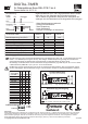
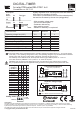
ON
1 2 3 4
Digital-Timer (component side)
Pushbutton
+
-
+
-
+
-
ON
1 2 3 4
LOAD
Pushbutton
+
-
5 bis 35V=
+
-
Max. 50V=
D1
Switching time S1 S2 S3 S4
(approx.)
4 sec. 0 0 0 0
8 sec. 1 0 0 0
15 sec. 0 1 0 0
30 sec. 1 1 0 0
1 min. 0 0 1 0
2 min. 1 0 1 0
4 min. 0 1 1 0
8 min. 1 1 1 0
16 min. 0 0 0 1
32 min. 1 0 0 1
1 hour 0 1 0 1
2 hour 1 1 0 1
4 h 15 m 0 0 1 1
8 h 30 m 1 0 1 1
17 hour 0 1 1 1
34 hour 1 1 1 1
Coding switch
Switch S
0 = OFF
1 = ON
Legal Notice
This data sheet was published by Conrad Electronic SE, Klaus-Conrad-Straße 1, D-92240 Hirschau (www.conrad.com). All rights,
including translation, are reserved. Reproductions of any kind, e.g. photocopy, micro filming or recording in electronic data processing
systems require the written approval of the publisher. Reprints - in whole or part - are prohibited.
This data sheet comply with the technical state of the art at the time of print. Technical and equipment changes reserved.
© Copyright 2012 by Conrad Electronic SE *03/12-NB
Connection assignment
Operating voltage voltage of the REL-PCB(‘s)
D1= 1N4001 (required for inductive load)
Separate voltage supply
Input Output for supply