
User manual

30
14th Da
y
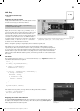
In the Advent calendar toda
y
•1x modelling clay re
d
•1x resistor 20MOhm
M
odelling clay contac
t
T
oday, you will use the enclosed modelling clay as an input
and change the background colour of an area in the App when
t
he modelling clay is touched
.
C
omponents
:
1x board, 2xpieces o
f
modelling clay, 1xresi
-
s
tor 20MOhm, 3xjumper
(
different lengths
)
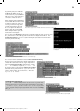
Th
is is
h
ow sensor contacts wor
k:
Th
e pin switc
h
e
d
as input is connecte
d
to +3.3V via an
extremely high-Ohmic resistance
(
20MOhm
)
, so that a weak
s
ignal that is still clearly de
fi
ned as high is pending. A person
who is not
fl
oating
f
reely in the air is always grounded and
s
upp
l
ies a
l
ow
l
eve
l
t
h
roug
h
e
l
ectrica
ll
y con
d
uctive s
k
in. W
h
en
th
is person touc
h
es a sensor contact, t
h
e wea
k
h
ig
h
signa
l
is
overlaid by the much higher low level o
f
the
fi
ngertip, pulling
th
e pin to
l
ow
l
eve
l
.
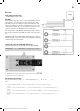
T
he actual height of the resistance between hand and ground
depends on many things, including shoes and fl oor. Barefoot
in wet grass offers the best ground connection, but stone fl oors
usually work well, too. Wood fl oors insulate more strongly, and
plastic fl oorings often even are positively charged. For the circuit to
w
or
k
at a
ll
times, an a
dd
itiona
l
groun
d
contact is insta
ll
e
d
in eac
h
circuit, simi
l
ar
l
y to sensor
b
uttons at e
l
evators an
d
d
oors. W
h
en
it an
d
t
h
e actua
l
sensor are touc
h
e
d
at t
h
e same time, t
h
e groun
d
connection is made in any case
.
Putty con
d
ucts current a
b
out as we
ll
as t
h
e
h
uman s
k
in
d
oes. It
can easily be
f
ormed in any desired shape, and a putty contact
is much easier to grasp than a simple piece o
f
wire. The area on which the hand touches the contact is
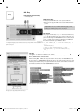
much larger. Thus, a “loose contact” is less likely to occur. Cut a piece o
f
about 10cm
f
rom the switchin
g
wire, remove the insulation
f
or about 1cm on either end and push one end into a piece o
f
modellin
g
clay. Push the other end into the board as illustrated
.
The IoT-board has analogue inputs that are very suitable
f
or sensor contacts. Analogue inputs supply
values between 0
(
low level
)
and 1023
(
high level
)
: Values between 100 and 200 are good limits to tell
apart contacte
d
an
d
non-contacte
d
sensor contacts.
T
h
e S
k
etc
h
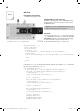
The program
f
or this day is Tag14.
i
no
a
n
d
l
ocate
d
in
d
irectory
T
ag1
4
. The actual
f
unction in this sketch
can be programmed with a
f
ew lines. ana
l
ogRea
d
reads in the value; i
f
it is below the threshold, a text
will
be
se
n
t
vi
a
t
h
e
wir
e
l
ess
in
te
r
face
wi
t
h
H
C05.
p
r
i
n
t
:
void loop
()
{
sensorValue = analogRead
(
sensorPin
);
if
(
sensorValue < 256
)
{
HC05.print
(
“LOW\n”
);
delay
(
1000
)
;
}
}
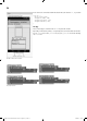
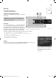
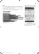
T
he end o
f
the two protruding jumpers goes into a piece o
f
modelling clay each. Best shape it
into a small, round ball. The modelling clay contact at A3 is used as the input
.
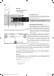
Circuit dia
g
ram for sensor contacts on the IoT-boar
d
14. Day
15007-3 Conrad Adventskalender Internet of Things 2017_en.indd 3015007-3 Conrad Adventskalender Internet of Things 2017_en.indd 30 13.08.2017 17:03:1413.08.2017 17:03:14