5007-3 Conrad Adventskalender Internet of Things 2017_en.indd 1 13.08.
Alle Versuche im Überblick Internet of Things Advent Calendar 2017 .................... 3 12th Day...................................................................27 Source codes and additional information . . . . . . . . . . . . . . . . . . . . . . . . 3 Background knowledge on the components . . . . . . . . . . . . . . . . . . . . . . 3 LEDs . . . . . . . . . . . . . . . . . . . . . . . . . . . . . . . . . . . . . . . . . . . . . . . . . . . . 3 Resistors and their colour codes . . . . . . . . . . . .
Internet of Things Advent Calendar 2017 If Cisco has its way, more than 50 billion linked devices will be used by 2020; even more optimistically, Intel expects 200 billion devices1.
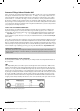
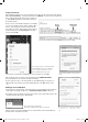
In which direction is the LED connected? The two connection wires of an LED are differently long. The longer one is the plus pole, the anode, the shorter one the cathode. It‘s easy to remember: The plus has one dash more than the minus and therefore also makes the wire a bit longer. Most LEDs are also flattened on the minus side, like a minus sign. It‘s easy to remember: Cathode = short = edge.
1st Day In the Advent calendar today 1. Day • 1 x IoT Bluething board2 Today, you will get to know the board with which you will implement the projects of the next 24 days. To prepare for the next days, you will install the driver for the USB connection, install the Arduino IDE and finally create your first program for the board. Chipset on the IoT-board The IoT-board comes with two chipsets. For program execution, the board has an ATmega328P.
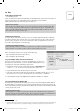
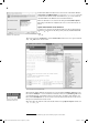
Download the Windows Installer for the current version of the Arduino IDE from www.arduino.cc/en/Main/Software or use the file arduino-windows.exe from the downloads for the Advent calendar. Under Windows 10, you can also download the Arduino IDE from the Windows Store and install it from there. Make sure that all boxes are checked in the dialogue field Installation Options. Depending on the Windows configuration, the user account control must be confirmed.
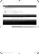
Testing the IoT-board After updating the firmware, you can now test the board. For this, open the serial monitor of the Arduino IDE via Tools/Serial Monitor. Set the data transmission to 57600 Baud. Now you should see legible text in the output window. Finally, there will be an output saying Configuration successful!, followed by information on the wireless network. Now you can use your Android Smartphone to test whether you can see the wireless network.
Below the source code window, you can see the outputs of the Arduino IDE when compiling and uploading. If the LED does not flash, look at the error messages in the Arduino IDE. The connection to the IoT-board has failed here. In this case, you have chosen the wrong port; this can be fixed quickly in the menu itemTools/Port. Always use the IoT-board in AT mode The IoT-board has a Jumper. This jumper must be set to AT for all projects in this calendar.
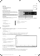
2nd Day 2. Day In the Advent calendar today • 1 x board (SYB 46) • 1 x jumper cable Measuring analogue values Today, you will program a Sketch in the Arduino IDE to read out the values of an analogue input. The values will be graphically displayed by text output. Components: 1 x board, 1 x jumper cable (male – male) The program The program for this day is called Tag02.ino and located in directory Tag02 within the download archive. The jumper cable serves as an antenna.
3rd Day 3. Day In the Advent calendar today • 1 x LED red with dropping resistor • 1 x switching wire Flashing light Today, you will make an LED flash at a frequency of 2 Hz. Components: 1 x board, 1 x LED red with dropping resistor The program The program for this day is called Tag03.ino and located in directory Tag03. const int ledPin = 2; int ledState = LOW; You do not need any separate resistor, since the LED already has an integrated one.
4th Day In the Advent calendar today 4. Day • 1 x LED yellow with dropping resistor Alternating flash Two LEDs flash alternatingly. Components: 1 x board, 1 x LED yellow with dropping resistor, 1 x LED red with dropping resistor The program The program for this day is called Tag04.ino and located in directory Tag04.
5th Day 5. Day In the Advent calendar today • 1 x LED green with dropping resistor Traffic light Today’s project is a traffic light that is created with the graphical development interface Snap!. Components: 1 x board, 1 x LED green with dropping resistor, 1 x LED yellow with dropping resistor, 1 x LED red with dropping resistor, 1 x jumper Installing Snap! and preparing the IoT-board Starting at three LEDs, things get a little crowded, so that GND is separately connected to the upper strip.
6th Day In the Advent calendar today 6. Dayy • 1 x LED blue with dropping resistor Connection to the IoT-board Today, you will connect your Smartphone to the IoT-board and switch the blue LED on and off again with your Smartphone. Components: 1 x board, 1 x LED blue with dropping resistor Installing the App for control Today, you will not use a dedicated App yet, but control the board via the free App Serial Bluetooth Terminal from the App-Store Google Play.
When the IoT-board receives data, the following loop will be performed: while(HC05.available() > 0){ … Text=””; } Now enter a call for the function to be programmed hookRec(Text) before the last line: while(HC05.available() > 0){ … hookRec(Text); Text=””; } The name of the network is Bluething103 and the password is 1234. In this function, you can now output the received text via the wireless interface: void hookRec(String text) { if (text.startsWith(“echo”) || text.startsWith(“Echo”)) { HC05.
7th Day In the Advent calendar today 7. Day • 1 x potentiometer, 15 kOhm Controllable running light Today’s project is a running light the speed of which can be controlled with a potentiometer. Components: 1 x board, 1 x LED green with dropping resistor, 1 x LED yellow with dropping resistor, 1 x LED red with dropping resistor, 1 x 15-kOhm-potentiometer, 4 x jumper (different lengths) The program The program for this day is called Tag07.ino and located in directory Tag07.
8th Day 8. Day In the Advent calendar today • 1 x piezo Outputting sounds through the App An App can be used to output sounds on a piezo. Components: 1 x board, 1 x piezo The two wires of the piezo are connected to D2 and GND. The rest is solved via the software. Development environment for the Apps The IoT-board in this Advent calendar is controlled using the Serial Bluetooth Terminal App that has been used before, and the self-developed Smartphone-Apps for the Android operating system6.
The interface is not yet available in German. In order to test your self-developed App during development, you need to install the free App MIT AI2 Companion from the Google Play Store on your Smartphone. After starting, you need to enter the code for your App; for this, you need to create an App first. Your first App with AI2 Now click the start button Start new projectt and enter the name Meine_erste_App. Note that the name must not contain any spaces.
The window is broken up into several areas. On the left, you can see the interface elements available for the App in the area Pallet. Next to it, you can see the interface of your App in the Viewer . Components shows the components used in your App and Properties the properties of the currently selected component. Now draw text in the form of a label into the window. Adjust the label by setting Width to Fill parentt and TextAlignmentt to center:I. Now the label is centred horizontally.
Text to. Either insert the element twice or insert the element once and copy it via the context menu (right mouse button) of the component. Components have a context menu. Use Duplicate to copy the selected component. Now insert the two components within the previously inserted elements (when Button1.TouchDown and when Button1. TouchUp). Now you still need text content. For this, select the empty element from the category Textt (top-most element).
Controlling the piezo with the App In order to control the IoT-board with an App, you need a Sketch on the board that reacts to the commands from the App and an App. Today, we want to control the enclosed piezo with an App. The Sketch you need for this is Tag08.ino in the directory Tag08. Load this Sketch onto the IoT-board. The Sketch is based on the already-used file Vorlage.ino.
Programming takes place within the tab Blocks. The Timer sets the connection status. The property isConnected can be used to check if the App is connected to a Bluetooth device. When clicking the button Connect, the list of available Bluetooth devices will be displayed. If the list is empty, you need to go back into the App, where you will automatically be asked for the access rights for the Bluetooth interface. Enter the password 1234. When clicking the button again, the list should now be displayed.
Testing the App Now start the App via Connect/AI Companion and call the App MIT AI2 Companion on your Android-Smartphone. Scan the QR-Code or enter the code and start the App via connect with code. The App now starts. Touch Connect. Now you can connect to the IoT-board. The connection is not active yet at first. The App is now connected to the IoT-board. If you touch Play sound now, the IoT-board will play a melody via the piezo. 15007-3 Conrad Adventskalender Internet of Things 2017_en.indd 22 13.
9th Day In the Advent calendar today 9. Day • 1 x RGB-LED with dropping resistor RGB-LEDs A normal LED is always lit in only one colour. The RGB-LEDs used in the Advent calendar can be lit in different colours. Generally, three LEDs with different colours are installed in a transparent housing here. Each of these three LEDs has its own anode, through which it is connected to a GPIO pin. The cathode, which is connected to the ground line, is only present once.
Each colour has its own function within the Sketch. Below, the function rot() is presented: void rot() { Serial.println(„Red“); analogWrite(redPin, HIGH); analogWrite(greenPin, LOW); analogWrite(bluePin, LOW); } The App The associated App is contained in file RGB.aia. Import the file into AI2. Depending on the buttons pushed, a corresponding text is sent via the Bluetooth interface: For red, red\n is sent, for blue, blue\n is sent, for green, green\n is sent and for switching off, off\n is sent.
10th Day In the Advent calendar today 10. Day • 1 x button Displaying the push of a button Today, your IoT-board will react to a mechanical push of a button and send a message to the wireless interface. Components: 1 x board, 1 x button, 1 x potentiometer, 5 x jumpers (different lengths) Digital pins can not only output data, e.g. via LEDs, but also be used to enter data. We use a button for input in today’s project that is directly connected to the board.
11th Day 11. Day In the Advent calendar today • 1 x switching wire LED echo by App Today’s project is an LED echo. Set a sequence with two interfaces in the App. The LEDs on the board will flash in this sequence. Components: 1 x board, 1 x LED red with dropping resistor, 1 x LED green with dropping resistor, 1 x jumper The Sketch The program for this day is Tag11.ino and located in directory Tag11. The App determines the echo sequence. The text is output in the following form: RNNGNN.
12th Day In the Advent calendar today 12. Day • 1 x LED orange with dropping resistor Setting the running light speed by App In today’s project, you will control the speed of a running light with the App. Components: 1 x board, 1 x LED red with dropping resistor, 1 x LED orange with dropping resistor, 1 x LED green with dropping resistor, 1 x jumper The Sketch The program for this day is Tag12.ino and located in directory Tag12.
13th Day 13. Day In the Advent calendar today • 1 x LED pink with dropping resistor Adjusting RGB via a slider in the App In addition to displaying basic colours, an RGB-LED can also display graduations. You can use an App to set the colour of the RGB-LED precisely. Components: 1 x board, 1 x RGB-LED with dropping resistor, 1 x LED pink with dropping resistor, 1 x jumper The Sketch The pink LED is used to signal that the connection is active. The program for this day is Tag13.
The App The development environment for today’s App is the AI2. For this, import the file RGB_ Slider.aia. Use three sliders to set the value for the respective colour. Push Set colour to send the value of the three sliders to the IoT-board. Touching Set colour will cause the text to be submitted to be composed in the variable farbe. Bluetooth.SendText sends the text via the wireless interface. The string is composed via join, which can also be nested.
14th Day 14. Day In the Advent calendar today • 1 x modelling clay red • 1 x resistor 20 MOhm Modelling clay contact Today, you will use the enclosed modelling clay as an input and change the background colour of an area in the App when the modelling clay is touched. Components: 1 x board, 2 x pieces of modelling clay, 1 x resistor 20 MOhm, 3 x jumper (different lengths) This is how sensor contacts work: The end of the two protruding jumpers goes into a piece of modelling clay each.
The App Today’s App Knete_Schalter.aia contains a label that has an orange background colour at first. To check if a text has been sent via the Bluetooth interface, it must be periodically reviewed whether a text is present. This is done with the existing timer. Configuring blocks The elements in the area Blocks in the block editor can partially be configured. The configuration takes place using the blue cogwheel at the component. The if-block also supports else and else-if.
15th Day 15. Day In the Advent calendar today • 1 x resistor 20 MOhm Differentiable modelling clay contacts Now use two modelling clay contacts and display in the App which contact has been pressed. Components: 1 x board, 3 x pieces of modelling clay, 2 x resistor 20 MOhm, 4 x jumper (different lengths) The Sketch The program for this day is Tag15.ino and located in directory Tag15. As on day 14, activation of the modelling clay contact is read via analogRead.
16th Day In the Advent calendar today 16. Day • 1 x flashing LED red with dropping resistor Controlling the flashing LED with the App Switch the flashing LED on with a button and off again with another button. Components: 1 x board, 1 x flashing LED red with dropping resistor The Sketch The program for this day is Tag16.ino and located in directory Tag16. The Sketch reacts to On and Off from the wireless interface: if (Text.startsWith(“On”) || Text.startsWith(“ON”) || Text.
17th Day 17. Day In the Advent calendar today • 1 x potentiometer Display of the resistor value Today, you will measure the value of a potentiometer via an analogue input and can output the value in an App. Components: 1 x board, 1 x potentiometer 15 kOhm, 4 x jumper (different lengths) The Sketch A potentiometer is just an analogue sensor from the program’s point of view. The program for this day is Tag17.ino and located in directory Tag17.
18th Day In the Advent calendar today 18. Day • 1 x jumper cable RGB-running light This App controls the flashing duration of an RGB-LED. The LED will flash in alternating colours. You can also stop its flashing again. Components: 1 x board, 1 x RGB-LED with dropping resistor, 1 x jumper cable The Sketch The program for this day is Tag18.ino and located in directory Tag18. The Sketch reacts to the text stop and to a set number. stop will switch off the RGB-LED.
19th Day 19. Day In the Advent calendar today • 1 x jumper cable App to select hardware Apps Today, we will combine two functions in one circuit: Playing a sound with the piezo and flashing of an RGB-LED. Use the App to select the corresponding function. Components: 1 x board, 1 x RGB-LED with dropping resistor, 1 x piezo, 1 x jumper cable The Sketch The program for this day is Tag19.ino and located in directory Tag19.
20th Day In the Advent calendar today 20. Day • 1 x NTC Heat sensor in the App Today’s project uses an NTC for temperature measuring. You can test this project well, e.g. by approaching a candle on the Advent wreath with the NTC. Components: 1 x board, 1 x NTC, 1 x potentiometer 15 kOhm, 6 x jumper (different lengths) The Sketch The program for this day is Tag20.ino and located in directory Tag20. The Sketch is set up very simply.
21st Day 21. Day In the Advent calendar today • 1 x photo transistor • 1 x resistor 1 kOhm Measuring brightness and darkness in the App Now you have another sensor for your projects. You can use the photo transistor to display brightness and darkness. You will learn how to today. You can use this knowledge to build a light barrier, which will give you an alarm system with a display in an App.
22nd Day In the Advent calendar today 22. Day • 1 x moisture sensor • 1 x resistor 1 kOhm Moisture measurement Today, you get another sensor: a moisture sensor. You can use it to measure moisture. Components: 1 x board, 1 x moisture sensor, 1 x resistor 1 kOhm, 3 x jumper (different lengths) The Sketch The program for this day is Tag22.ino and located in directory Tag22.
23rd Day 23. Day In the Advent calendar today • 1 x jumper cable Code breaker Today’s project is a little game: You will set a code in an App. Then you will submit this code to the IoT-board. Now the code must be entered with the button. If the code has been entered correctly, the red LED will light up and the App will display that the code has been entered correctly. Otherwise, the red LED will not light up and the App will display that the code has not been entered correctly.
Since three buttons are needed for this game, there are also three when.Click blocks. The texts from the IoT-block are received in the periodic timer. The timer that was used for displaying the connection status is used for this. If YES is received, the background colour is switched to green; otherwise, it will be red. 15007-3 Conrad Adventskalender Internet of Things 2017_en.indd 41 13.08.
24th Day 24. Day In the Advent calendar today • 1 x button Reaction game We will end this Advent calendar with a little reaction game. You can start the game with a button in the App. The LED on the board comes on; once the LED goes out, you need to push the button. The duration is displayed on the App. Components: 1 x board, 1 x button, 1 x LED green with dropping resistor, 1 x potentiometer 15 kOhm, 5 x jumper (different lengths) The Sketch Today’s circuit is similar to that of the previous day.
To start the game, the block when startButton.click is evaluated when the button Start game is clicked, and the text START is submitted via the wireless interface. The wireless interface should always be read out with a timer. You cannot tell precisely when a data package will arrive. Merry Christmas! 15007-3 Conrad Adventskalender Internet of Things 2017_en.indd 43 13.08.