
User manual
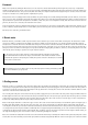


Info: the functionality of this circuit cannot be easily understood. Behaviour of an ideal operational amplifier
would be quite different. However, specific features of the bipolar op-amp with PNP input stages are used in this
case. The input current is about 30 nA, so there is a voltage drop of 10 mV at the inverting input and only 3 mV at
the non-inverting input. The difference is sufficient to achieve a steady idle state. The sensor must add at least
7 mV to change the state. When turning over to the 'red' state, the electrolytic capacitor raises the voltage at the (+)
input and maintains this state stable through feedback. Then it must charge to such an extent that the input
voltage drops below 3 mV, which lasts for about half a minute. Then the initial state turns over. This might reduce
the voltage at the input by some few volts below zero, which is already outside the normal operational range of
the op-imp. Below –0.5 V, the function of the op-imp is reversed. For a certain time feedback turns into negative
feedback and the circuit acts as an integrator. Therefore, the output state changes only slowly.
Mission: remove the electrolytic capacitor from the circuit and integrate the disk capacitor with 100 nF to speed up
the process. Modify the circuit so that flash of red light appears in response to every noise. 3 points.
14 Tone generator
Behind the 14th door, there is another 100 k
resistor (brown, black, yellow). Make now a signal generator producing a loud sound. In addition, the output signal
is indicated by the green LED. At first you only see a uniform light. However, if you perform quick eye motions, you can detect that the LED rapidly switches on and
off.
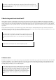
Info: a voltage divider with two equal resistors applies half the operating voltage to
the (+) input of the op-amp. An additional resistor at the output creates feedback,
which keeps output state either at high or at low voltage. In addition, there is a
negative feedback to the inverting input, which is, however, delayed by a capacitor.
The output state toggles every time after the capacitor has charged or discharged for
long enough. Thus, regular oscillations appear.
Mission: replace the 100-k
resistor in the negative feedback by a significantly
smaller resistor of 4.7 k
. It will make the tone, pitch much higher: 2 points.
15 Acoustic temperature sensor
Behind the door number 15, there is a 10 k
resistor (brown, black, orange), which will be used now instead of the 100 k
resistor. Thereby a higher tone is
created. Touch the capacitor by two fingers. It is slightly warmed up thereby, which causes a tone change.
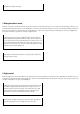
Info: most electrical components change their properties with temperature change.
This behaviour is especially pronounced with many ceramic capacitors. More partic-
ularly, close to room temperature of 20°C the capacity reaches a maximum and drops
markedly at higher and much lower temperatures. Therefore, warming up by fingers
leads to a higher tone frequency.