
User manual


again in the interface view. Now a simple tap is enough to cause the LED to stay lit.
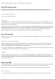
Day 6: The hardware button
In yesterday's test, you realised a simple control of an LED using the Blynk app. Today you'll see that the control works in both directions. The
push-button switch behind today's door really comes in handy for this purpose. With it, you can expand yesterday's circuit as follows:
The new layout with push-button switch at D7
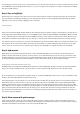
You can scan the interface for today here:
The QR code for Day 6
In the Blynk app, there is a virtual currency labelled Energy. It prevents you from using very extensive projects or many smaller projects in the
app at the same time. For you, that means that you may have to delete old projects starting on Day 8. But you can save your adapted project by
creating a QR code and saving it somewhere.
As always, you'll find today's programme on the website. Today, too, the WLAN data and the AUTH TOKEN of the project must be transferred into
the programme. Each project has its own token, so you have to have the code re-sent or transfer it into the programme manually. After you start
the interface with the Play button, you can again cause the LED on the breadboard to light up by tapping on the button. But you also see a
change in the app if you push the button on the breadboard. Thus, the connection is possible in both directions.
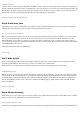
Day 7: Analogue write
Behind today's door is a potentiometer. You can use it to transfer analogue messages to the Blynk app. To do this, you need to build the circuit
according to the picture.
The potentiometer uses the lower wire for the connection to A0.
Things can get a bit tight when constructing with the MicroUSB cable. So that everything connects, you first have to disconnect the board from
the cable and place the jumpers to be as flat as possible. You also need to be aware that this time the VCC is not applied to the track at the
bottom of the image; instead, the track is intended for the connection at Pin A0.
You can import the Blynk interface as usual with the QR code. You'll find the programme on the website. Don't forget to enter the new token and
your WLAN data before you upload the programme to the NanoESP board.
Today's interface
The measured data are now received approx. once a second and shown in the graph widget. You can affect the measured values by turning the
potentiometer. Note that the maximum value is 1023. The reason is that the NanoESP reads the voltage with a resolution of 10 bits. These are
formed from a voltage range between 0 and +5 V. The potentiometer acts as a voltage divider in this process, so that voltages between 0 and 5 V
can be adjusted at the centre pin.
Day 8: Virtual LEDs
In the test for the sixth day, you saw how a push button on the hardware side can be mapped on a button in the app. However, another widget,
namely the LED widget, is much simpler for this instance. In today's test, you'll see how to use it properly and what options it offers.
Behind today's door is another 1-kohm resistor that is important for later tests. Today the circuit from yesterday is expanded by a button.
The layout of today's project
You can insert the interface again via QR code. However, the Blynk app may then give you a notice that you don't have enough energy. As