
User manual

Day 5
Today on the Advent calendar
• Red LED
Dimming the LED
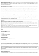
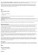
Components: 1xbreadboard, 2xred LED, 2x220-ohm resistor (red-red-brown), 3xconnection cable
LEDs are typical components for the output of signals in digital electronics. They can take on two different states: on and off, 0 and 1 or false and
true. The same is true for the digital pins defined as outputs. Thus, in theory, it would not be possible to dim an LED.
However, it is possible to use a trick to regulate the brightness of an LED at a digital pin. If one allows an LED to flash fast enough, the human
eye no longer perceives it as flashing. The technology known as pulse width modulation (PMW) generates a pulsing signal that switches on and
off in very short intervals. The voltage of the signal always remains constant; only the ratio between the false level (0V) and true level (+3.3V) is
changed. The duty cycle determines the ratio of the length of the switched-on state to the total duration of a switch cycle.
The smaller the duty cycle, the shorter the time is that the LED is lit within a switch cycle. The LED thus appears darker than an LED that stays
switched on.
Pins for PWM signals
Pins 3, 5, 6, 9, 10, 11 are marked on the Arduino with a "~" symbol. These pins can be used for pulse width modulation.
The programme
The programme 05pwm01 dims the two LEDs brighter and darker in a cycle. At the beginning, two variables are defined for this purpose: bright
designates the PMW value for the brightness of the LED and step gives the step width for dimming. The current values of both variables are
shown in real time at the top right of the platform.
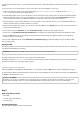
Now an infinite loop begins. As the first step in every pass, the current value of the variable bright is outputted as the PWM value at Pin5 and
then after a short delay also at Pin6. Then the value of the variable bright is increased by the value step.
In the next step, the programme checks whether the value of bright has reached the limits 0 or 100. In this case, an or block is inserted, which in
turn has space for two further queries. If at least one of these two is true, the or block returns the value true and the content of the if block is
executed.
Two equals queries check whether the variable bright has reached the value 0 or 100. If this is the case, the variable step is set to a new value.
Because Snap4Arduino does not offer the option to reverse the sign of a variable, we use the operator '-' and subtract the value of the variable
from 0, which gives the same result.
At the end, the program waits 0.025 seconds. Then the infinite loop begins again and delivers the LEDs a new PWM value.
Day 6
Today on the Advent calendar
• 2xconnection cables
These connection cables will not be needed until the next few days.
Mixing colours with PWM
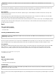
Components: 1xbreadboard, 1xRGB LED, 3x220-ohm resistor (red-red-brown), 4xconnection cable
The programme
The programme 06pwm02 dims the colour components of an RGB LED brighter and darker in a cycle. Various mixed colours are thereby generated.
The current values of all variables are shown in real time at the top right of the platform.