
User manual

Resistors and their colour codes
Resistors are used to limit current to sensitive electronic components and also as series resistors for LEDs. The unit of measurement for resistors
is the ohm. 1,000 Ohm equals one kilo-ohm, abbreviated kOhm. 1,000 kOhm equals one mega-ohm, abbreviated MOhm. The letter omega Ω is
also frequently used for the unit ohm.
The coloured rings on the resistors indicate the resistance value. With some practice, they are much easier to recognise than teeny tiny numbers
that one can still find on very old resistors.
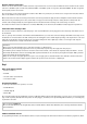
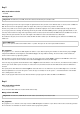
Most resistors have four such coloured rings. The first two coloured rings indicate the digits, the third a multiplier and the fourth the tolerance.
This tolerance ring is usually in gold or silver, colours that do not appear on the first rings. Thus, the reading direction is always clear. The
tolerance value itself plays hardly any role in digital electronics. The table shows the meanings of the coloured rings on resistors.
The direction in which a resistor is installed does not matter. With LEDs, on the other hand, the installation direction plays an important role.
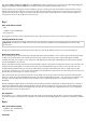
Connection cables and jumper wire
The coloured connection cables have a thin wire plug on each end, with which they can be plugged into the socket strips of the Arduino and on
the breadboard.
Later on, a jumper wire is included on the Advent calendar. With this wire, you create short connection bridges, with which contact strips on the
breadboard are connected. Cut the wire with a small pair of side-cutting pliers to the suitable length depending on the experiment. In order to be
better able to plug the wires into the breadboard, we recommend cutting them off at a slight angle so that a sort of wedge results. Strip the
insulation from both ends to a length of about half a centimetre.
Precautions
Never connect any random Arduino pins to each other and wait to see what happens.
Not all Arduino pins can be freely programmed. Some are permanently set up for the power supply and other purposes.
Some Arduino pins are directly connected to connections of the microcontroller; a short circuit can completely destroy the Arduino – at least
theoretically. The Arduino boards are astonishingly stable against circuit faults. If one connects two pins together through an LED, a protective
resistor must always be placed between them.
Always use the 3.3 V pin for logical signals. The 5 V pin is used to supply power to external hardware. Here (almost) as much current can be
drawn as the connected mains adapter supplies. However, this pin must not be connected to a digital input.
Day 1
Today on the Advent calendar
• Breadboard (SYB 46)
• Red LED
• 220-ohm resistor (red-red-brown)
• 2xconnection cables
Preparing the Arduino
In order to put the Arduino into operation, one needs:
• PC with Windows
• USB cable (Type B)
• Arduino IDE
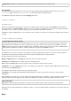
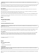
The connection between the PC and Arduino occurs via a USB cable with the almost square Type B plug on one side. You do not need to buy this
type of cable separately; virtually all modern printers use this plug type, and while you are experimenting with the Arduino, you are hardly going
to print at the same time.
Don't connect the Arduino yet
Do not connect the Arduino to the PC right away; rather, install the Arduino software first. Otherwise, there could be problems later with the
driver installation.
Software installation in brief
For programming the Arduino, the manufacturer delivers a very clear development environment in which one can write the programmes, which