
User manual
bounce is significantly faster, the counter always recognizes only one pulse. This reliable 4-bit counter
can also represent larger numbers if one uses the higher-valued outputs. In all, it takes 16,384 button
presses for all outputs, including Q14, to return to their starting state.
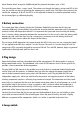
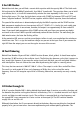
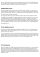
20 Multi-flash pattern
Open Door Number 20 and take out a 1kΩ resistor (brown, black, red). With it, you have the series
resistor suitable for maximum brightness. This time, very special flash patterns should result. Each of
the yellow LEDs flashes four times in a row and then pauses while the other LED flashes. The two red
LEDs each flash once and then pause longer.
The special flash pattern occurs because the LEDs conduct current in only one direction. The lower
yellow LED lights up only when Q7 is already switched off and Q4 is already on. Thus, one can create
very different patterns with LEDs at additional outputs. At any rate, it is permitted in this case to
connect LEDs even without resistors directly between two outputs. At an operating voltage of 9 V, the
output transistors of the 4060 have an on resistance of about 300Ω. Thus, both outputs together have
a resistance of 600Ω. The result is an LED current of around 10mA, which is still significantly below
the permitted 20mA.
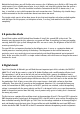
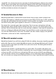
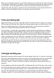
21 Four brightness levels
You will find an especially bright green LED behind Door Number 21. In this test, it should become
brighter by stages. There are four brightness levels, 0, 1, 2 and 3, which run in sequence. The red LED
shows the pulse at the same time.
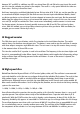
The circuit corresponds in function to a digital-analogue converter, which converts digital numbers into
analogue voltages or currents. Q7 switches a large current through the 1-kΩ resistor on and off. A large
brightness level results. In addition, Q6 switches a smaller current through the 2.2-kΩ resistor on and
off, which adds to the larger current. The result is thus a total of four brightness levels.
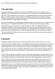
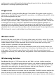
22 Colour flasher
Behind Door Number 22, a 100µF (microfarad) electrolytic capacitor appears. It has a thousand times
greater capacity than the 100 nF disk capacitor you have used up to now. One thus achieves large
charging currents that can be seen as LED light flashes. Here green and yellow light flashes occur in a
longer interval. Each flash gradually subsides in about half a second. So that one does not have to wait
too long for the flashes, the smaller 10 nF capacitor is installed in the oscillator. The red LED shows the
divided pulse signal.