
User manual
usually generate a precise 50-Hz cycle by directly touching the input. In this test, the result is that the
blink pattern is run through significantly more slowly.
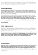
17 Light sensor
Another yellow LED is hiding behind Door Number 17. Both yellow LEDs together should now form a
light sensor. If a lot of light falls on the yellow LEDs, one receives a fast flickering of the red LEDs. In the
dark, the flashing becomes very slow.
The oscillator works again with the extremely small capacitor of two contacts of the breadboard. Thus,
even with a high resistance of 22 MΩ, a high frequency results. The two yellow LEDs form a resistor that
is much higher still, however, yet one that is dependent on the ambient brightness. Both LEDs are
connected in series such that one of the two always operates in the back direction. Thus, there should
actually not be any current flowing. However, when light falls on the LED crystal, the LED acts like a
photodiode. Now a small amount of current flows even in the back direction. The more light falls on the
LEDs, the larger this current is, and the higher the oscillator frequency becomes.
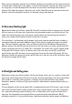
18 Button counter
Behind the 18th door you will find a 4.7kΩ resistor (yellow, violet, red). With it, another LED can now
be operated with greater brightness. In all, four LEDs create four bits of a binary number. Therefore, 16
numbers between 0 and 15 can be represented. But this time the counter does not run by itself;
instead, the pulse is generated by the push-button switch.
After every eight button presses, a level change should be observable at Q4. Actually, however, the
change is significantly more frequent. In most cases, it takes three or four button presses for a change
at the outputs. This is due to the contact bounce of the switch, where the contacts bounce back
multiple times on closing. Thus, with one push, one generates a short series of impulses, which are all
counted.
19 Debouncing the button
Door Number 19 reveals a 2.2kΩ resistor (red, red, red). With it, you have a further resistor for a
greater brightness. The significant change to the test consists in an additional capacitor parallel to the
input OSC1. It serves to debounce the button. Thus, with each button press, exactly one pulse is now
counted. After every eight pulses, the output Q4 changes. And after every 128 pulses, the counter
returns to its starting state. One thus has an reliable event counter.
The 4060 can count pulses that are shorter than one microsecond. The 100nF capacitor, together with
the 10kΩ resistor, has a time constant of one millisecond, which is a thousand times longer. That is
thus how long it takes for the capacitor to discharge after the contact opens. However, since the contact