
User manual
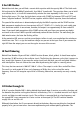
9 An LED flasher
Behind the ninth door, you will find a ceramic disk capacitor with the capacity 100 nF. The label reads
104 and stands for 100,000 pF (picofarads), thus 100 nF (nanofarads). The capacitor allows you to build
an oscillator, that is, a circuit that automatically switches the state repeatedly. In this case, a slow
flashing light occurs. This time, the high-ohmic resistor with 22MΩ lies between OSC1 and OSC2 and
forms a negative feedback. The 10 kΩ resistor, together with the 100nF capacitor, forms the feedback.
The speed of the switch-over is determined primarily by the 100nF capacitor and the 22MΩ resistor.
Both components together have a time constant of 0.1µF
*
22MΩ = 2.2s. And in fact, each stable state
lasts about two seconds. In one minute, therefore, the output is on approximately 15 times and off 15
times. If you touch both connections of the 22-MΩ resistor with your finger, you connect your body's
resistance in the scale of 1MΩ in parallel and thereby reduce the time constant. The more firmly you
hold onto the wires, the faster the flashing will be.
At the protective LED, one can see that current begins to flow in each case even before the switch-over
into the on state. This is a sign that medium voltages are present at the input. Even if you remove the
right LED from the output, you can see the regular increase of the current.
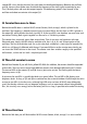
10 Fast flickering
Behind Door Number 10 you will find a 100kΩ resistor (brown, black, yellow). It should now replace
the previous 22MΩ resistor in the oscillator circuit. The flashing thus becomes so fast that it appears to
be a steady light. However, if you move the entire circuit back and forth, you will see lighted stretches
with interruptions. One can achieve the same effect by observing the layout in a moving mirror.
This time, the time constant is 100kΩ
*
100nF = 10ms. The output is on for 10 ms and off for 10 ms.
The result is a total period of 20 ms and a frequency of 50Hz, thus in the scale of the mains
frequency.One can still recognize up to 16Hz as flickering. Above that, one mostly sees only a steady
light.
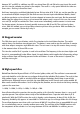
11 Divider through 16
A 10 nF capacitor (labelled 103) is hiding behind the eleventh door. It receives an auxiliary function and
lies between the positive and negative terminals of the battery. This is a standard measure in all digital
circuits and helps to avoid transient signals. The oscillator is converted back to a low frequency, and
the second LED is now connected to a series resistor at the output Q4. The LED switches between
roughly 30 s on and 30 s off.
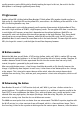
Differently from before, the IC now connects directly to the battery. Because everything has functioned
properly so far, you can now take a chance on experimenting even without polarity protection. The