
User manual


the IC. If everything is correct, both LEDs light up with the same brightness.
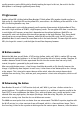
7 An open input
Open the seventh door and take out a resistor. It has 22 MΩ (22 mega-ohms, red, red, blue) and is
repeatedly used in the following tests in the oscillator circuit. The resistor is connected at the input OSC1
only on one side. One thus has an "open input". It is undefined whether one or zero is present; the LED is
either on or off. The result is random and can be affected by bringing your finger close to it. Even at a
distance of a few centimetres, the status of the gate can change. Static charges and the electrical fields
connected with them are responsible for this change.
You can turn the output on or off by tapping briefly on the input with your finger. If it is switched on, both
LEDs light up; if it is switched off, both LEDs can be off. The IC then consumes virtually no power.
However, there can be circumstances in which the output is indeed still switched off, but the IC
nevertheless consumes a certain amount of power. That is the case when the input voltage is neither
exactly zero nor exactly at the operating voltage but is somehow between these voltages. As long as the
input is touched, a half brightness can also be adjusted, whereby the LEDs actually flash very rapidly.
This lies in the 50-Hz AC fields of the electrical grid, which have the effect that your own body conducts a
small alternating current.
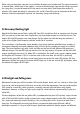
8 Feedback
Behind Door Number 8 you will find a 10 kΩ resistor (brown, black, orange). This time, it is used as
protective resistance at the input of the IC. The 22-MΩ resistor connects the second output to the input of
the oscillator circuit. The LED is either on or off; the result is unpredictable. An existing status lasts for a
random length of time. You can change the status, however, if you hold the free connection at the input
once at the positive and once at the negative. Beyond that, you can with some luck switch the LED on or
off if you simply tap the resistor with your finger or touch it with a piece of wire that you hold in your
hand.
In this circuit, two inverters are placed in series. An input zero state becomes a one state after the first
inverter and goes back to zero after the second inverter. Through the feedback, therefore, the zero state
is maintained at the input as well. Conversely, a one status at the output appears as one again and
persists. However, if the input is brought to the other state even very briefly, the circuit turns over. A
random impulse often suffices for this purpose, which occurs when you touch it because you are
electrically charged.This kind of circuit is also called a trigger circuit or a flip-flop. At the same time,
therefore, the circuit is also a digital memory with a storage size of 1 bit. If you take the right LED at the
output OSC3 out of the circuit, the circuit is practically de-energized even in the one state. The left LED
is thus permanently off regardless. Only in the switch-over moment does current flow. If you touch the
input, the left LED can light up.