
User manual
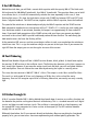
Behind the fourth door, you will find the wire necessary for all following tests. Build an LED lamp with
switch contact. Cut a suitable piece of wire, 4cm in length, and strip the insulation from the ends to a
length of about 5mm. This wire should be installed as connection to the LED. A shorter wire, 2cm
long, is installed as strain relief to protect the weak connection wires. The battery clip should always
remain connected so that the connections do not wear down too much.
The simple switch consists of two bare pieces of wire that touch together only when pushed together
with the finger. For this purpose, cut two pieces of wire, 2 cm long, and remove the insulation
completely.
5 A protective diode
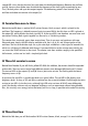
You will find another red LED behind Door Number 5. Install this second LED in the circuit. The
direction must be correct for this; otherwise, no current will flow. If everything has been put together
correctly, both LEDs light up. And although two LEDs are now in series, the brightness of the first LED
remains practically the same.
The new LED has an important function for the following tests. It serves as a protective diode and
should prevent an incorrect polarity of the battery. The component to be installed tomorrow, in
particular, reacts very sensitively to an incorrect polarity and should be protected against potential
faults. At the same time, the LED is a simple current indicator, with which one can recognize the correct
function of a circuit.
6 Digital circuit
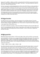
Open Door Number 6. Behind it you will find the most important part of this calendar, the CMOS-IC
4060. This IC with 16 pins contains a total of 14 divider flip-flops and a multifaceted oscillator circuit.
The connections 1 and 16 are on the left side and are marked with a groove. An additional note is
offered by the label, which one can read on the lower row (Pin 1 to Pin 8). Before the first use of the IC,
the connections must be aligned to be parallel because they still stand a bit too far to the outside after
the production. Push all pins on one side at the same time on a hard table surface to align them
sufficiently. Then place the IC correctly on the breadboard. Attention: if it is inserted the wrong way
round, the connections 8 (GND, negative) and 16 (VCC, positive) are switched, so that the operating
voltage is connected with the wrong polarity and the IC is destroyed. In this case, even the protective
diode at the positive terminal does not help, since it protects only against a battery that is connected
the wrong way round.
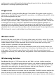
The first test uses a portion of the oscillator circuit at the connections 10 and 11. The input OSC1 is placed at
GND (negative terminal, logical zero). At the output OSC2 is the LED with its series resistor. If everything has
been assembled correctly, the LED lights up. The IC thus has the voltage switched on at the output (logical
one) and thereby inverts the input status. For most of the tests with the 4060, the reset input (RES) must
also be attached at GND. The red LED at the VCC connection indicates the operating current and protects