
Instruction manual


22
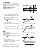
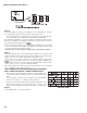
Step 6.
Set up the equipment according to the diagram above for calibrating the cold junc-
tion compensation. Note that a K type thermocouple must be used.
The 5520A calibrator is configured as K type thermocouple output with inter-
nal compensation. Send a 0.00°C signal to the unit under calibration.
The unit under calibration is powered in a still-air room with temperature 25±3°C.
Wait at least 20 minutes for warming up. Perform step 1 as stated above, then press
the scroll key until the display shows .
Press the scroll key for at least 5 seconds. The display will blink for a moment until
a new value is obtained. If the display didn't blink or if the obtained value is equal
to –5.00 or 40.00, then the calibration failed.
• Perform step 7 to calibrate gain of cold junction compensation if required.
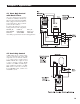
Step 7.
Setup the equipment same as step 6. The unit under calibration is powered in a still-
air room with temperature 50 ±3°C. Wait at least 20 minutes for warming up. The
calibrator source is set at 0.00°C with internal compensation mode.
Perform step as 1 stated above, then press the scroll key until the display shows
. Press the scroll key for at least 5 seconds. The display will blink for a
moment until a new value is obtained. If the display didn't blink or if the obtained
value is equal to –199.9 or 199.9, then calibration failed.
This setup is performed in a high-temperature chamber, therefore it is recommended
to use a computer to perform the procedures.
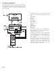
INPUT MODIFICATION AND RECALIBRATION PROCEDURES
FOR A LINEAR VOLTAGE OR A LINEAR CURRENT INPUT:
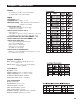
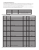
1. Remove R60 (3.3K) and install two 1/4W resistors RA and RB on the
control board with the recommended values specified in the following
table.
Low temperature coefficient resistors should be used for RA and RB.
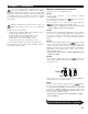
2. Perform step 1 and step 2 to calibrate the linear input zero.
3. Perform step 3 but send a span signal to the input terminals instead of
60mV. The span signal is 1V for 0–1V input, 5V for 0–5V or 1–5V
input, 10V for 0–10V input and 20mA for 0–20mA or 4–20mA input.
Step 8.
Set the LOCK value to your desired function.
Manual Calibration Procedures…
Resistor Chart