
Instruction manual


21
Do not proceed through this section unless there is a def-
inite need to recalibrate the controller. If you recalibrate,
all previous calibration data will be lost. Do not attempt recali-
bration unless you have the appropriate calibration equipment. If
t
he calibration data is lost, you will need to return the controller
to your supplier who may charge you a service fee to recalibrate
the controller.
Entering calibration mode will break the control loop.
Make sure that the system is ready to enter calibration
mode.
Equipment needed for calibration:
1. A high-accuracy calibrator (Fluke 5520A calibrator recom-
mended) with the following functions:
0–100mV millivolt source with ±0.005% accuracy
0–10V voltage source with ±0.005% accuracy
0–20mA current source with ±0.005% accuracy
0–300 ohm resistant source with ±0.005% accuracy
2. A test chamber providing 25°C–50°C temperature range
The calibration procedure described in the following section is a
step-by-step manual procedure.
Manual Calibration Procedures
• Perform step 1 to enter calibration mode.
Step 1.
Set the lock parameter to the unlocked condition
(LOCK=NONE).
Press and hold the scroll key until appears on the dis-
play, then release the scroll key.
Press the scroll key for 2 seconds, and the display will show
and the unit will enter the calibration mode.
• Perform step 2 to calibrate zero of A to D converter and
step 3 to calibrate gain of A to D converter.
Step 2.
Short the thermocouple input terminals, then press the scroll key
for at least 5 seconds. The display will blink for a moment and a
new value is obtained. If the display didn't blink or if the
obtained value is equal to -199.9 or 199.9, then the calibration
failed.
Step 3.
Press scroll key until the display shows . Send a 60mV
signal to the thermocouple input terminals in the correct polari-
ty. Press the scroll key for at least 5 seconds. The display will
blink for a moment and a new value is obtained. If the display
didn't blink or if the obtained value is equal to -199.9 or 199.9,
then the calibration failed.
• Perform both steps 4 and 5 to calibrate RTD function (if
required) for input.
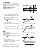
Step 4.
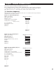
Press scroll key until the display shows . Send a 100
ohms signal to the RTD input terminals according to the connec-
tion shown below:
Chapter 5 Calibration
Press scroll key for at least 5 seconds. The display will blink for
a moment; if it does not, calibration failed.
Step 5.
Press the scroll key and the display will show . Change
the ohm's value to 300 ohms. Press the scroll key for at least 5
seconds. The display will blink for a moment and two values will
be obtained for RTDH and RTDL (step 4). If the display didn't
blink or if any value obtained for RTDH or RTDL is equal to -199.9
or 199.9, then this calibration failed.
• Perform step 6 to calibrate offset of cold junction compen-
sation, if required.
Manual Calibration Procedures, continued…