
Instruction manual


16
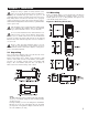
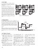
3–8 PV Shift
I
n certain applications it is desirable to shift the
controller display value (PV) from its actual value.
This can easily be accomplished by using the PV
shift function.
The SHIF function will alter PV only.
Example: A process is equipped with a heater, a
sensor, and a subject to be warmed up. Due to the
design and position of the components in the sys-
tem, the sensor could not be placed any closer to the
part. Thermal gradient (differing temperatures) is
common and necessary to an extent in any thermal
system for heat to be transferred from one point to
another. If the difference between the sensor and the
subject is 35°C, and the desired temperature at the
subject to be heated is 200°C, the temperature at the
sensor should be 235°C. You should enter -35°C to
subtract 35°C from the actual process display. This
in turn will cause the controller to energize the load
and bring the process display up to the set point
value.
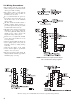
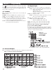
3–9 Digital Filter
In certain applications, the process value is too unstable to be
read due possibly to electrical noise. A programmable low-
pass filter incorporated in the controller is used to improve
this. It is a first-order filter with the time constant specified by
the FILT parameter. The default value of FILT is set at 0.5 sec-
onds before shipping. Adjust FILT to change the time constant
from 0 to 60 seconds. 0 seconds means no filter is applied to
the input signal. The filter is characterized by the following
diagram:
Note
The filter is available only for PV, and is performed for the
displayed value only. The controller is designed to use unfil-
tered signal for control even if the filter is applied. A lagged
(filtered) signal, if used for control, may produce an unstable
process.
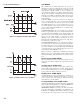
The controller will enter failure mode if
one of the following conditions occurs:
1. SBER occurs due to input sensor break
or input current below 1mA if 4–20 mA
is selected or input voltage below 0.25V
if 1–5V is selected.
2. ADER occurs due to the A-D converter
of the controller failing.
Output 1 and output 2 will perform the fail-
ure transfer function as the controller
enters failure mode.
Output 1 failure transfer, if activated,
will perform:
1. If output 1 is configured as proportion-
al control (PB≠ 0), and BPLS is select-
ed for O1FT, then output 1 will perform
bumpless transfer. Thereafter, the previ-
ous averaging value of MV1 will be
used for controlling output 1.
2. If output 1 is configured as proportion-
al control (PB≠ 0), and a value of 0 to
100.0% is set for O1FT, then output 1
will perform failure transfer. Thereafter,
the value of O1FT will be used for con-
trolling output 1.
3. If output 1 is configured as ON-OFF
control (PB=0), then output 1 will be
driven OFF if OFF is set for O1FT and
will be driven ON if ON is set for
O1FT.
Output 2 failure transfer, if activated,
will perform:
1. If OUT2 is configured as COOL, and
BPLS is selected for O1FT, then output
2 will perform bumpless transfer.
Thereafter, the previous averaging
value of MV2 will be used for control-
ling output 2.
2. If OUT2 is configured as COOL, and a
value of 0 to 100.0% is set for O2FT,
then output 2 will perform failure trans-
fer. Thereafter, the value of O1FT will
be used for controlling output 2.
3. If OUT2 is configured as alarm func-
tion, and O2FT is set to OFF, then out-
put 2 will go off. Otherwise, output 2
will go on if O2FT is set to ON.
Alarm failure transfer is activated as the
controller enters failure mode. Thereafter,
the alarm will transfer to the ON or OFF
state preset by ALFT.
3–10 Failure Transfer
Figure 3.7 PV Shift Application
Figure 3.8 Filter Characteristics