
Instruction manual


13
The ON-OFF control may introduce excessive process oscillation
even if hysteresis is minimized. If ON-OFF control is set (i.e.,
PB=0), TI, TD, CYC1, OFST, CYC2, CPB, and DB will be hid-
den and have no function in the system. The auto-tuning and
bumpless transfer functions will be disabled as well.
Heat only P (or PD) control: Select REVR for OUT1, set TI to
0. OFST is used to adjust the control offset (manual reset). O1HY
is hidden if PB is not equal to 0. OFST function: OFST is meas-
ured by % with a range of 0–100.0%. In the steady state (i.e.,
process has been stabilized), if the process value is lower than the
set point by a definite value, say 5°C, while 20°C is used for PB,
that is lower by 25%, then increase OFST 25%, and vice-versa.
After adjusting OFST value, the process value will be varied and
eventually coincide with set point.
Refer to section 3-12 “manual tuning” for the adjustment of PB
and TD. Manual reset (adjust OFST) is not practical because the
load may change from time to time and OFST may need to be
adjusted repeatedly. PID control can avoid this situation.
Heat only PID control: If REVR is selected for OUT1, PB and
TI should not be zero. Perform auto-tuning for the new process,
or set PB, TI, and TD with historical values. See section 3-11 for
auto-tuning operation. If the control result is still unsatisfactory,
then use manual tuning to improve control. See section 3-12 for
manual tuning. The unit contains a very advanced PID and Fuzzy
Logic algorithm to create a very small overshoot and very quick
response to the process if it is properly tuned.
Control Outputs, continued…
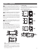
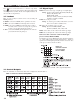
Heat only ON-OFF control: Select REVR for OUT1. Set PB
(proportional band) to 0. O1HY is used to adjust dead band for
ON-OFF control. The output 1 hysteresis (O1HY) is enabled
i
n case PB=0. The heat only on-off control function is shown
in the following diagram:
3.3 & 3.4 Alarm Figures, next page…
Cool only control: ON-OFF control, P (PD) control, and PID
c
ontrol can be used for cool control. Set OUT1 to DIRT (direct
action). The other functions for cool only ON-OFF control,
cool only P (PD) control, and cool only PID control are the
same as for heat only control except that the output variable
(and action) for cool control is inverse to heat control.
NOTE: ON-OFF control may result in excessive overshoot and
undershoot problems in the process. P (or PD) control will
result in a deviation of process value from the set point. It is
recommended to use PID control for heat-cool control to produce
a stable and zero offset process value.
Other setup required: O1TY, CYC1, O2TY, CYC2, O1FT
and O2FT are set in accordance with the types of OUT1 and
OUT2 installed. CYC1 and CYC2 are selected according to the
output 1 type (O1TY) and output 2 type (O2TY). Generally,
select 0.5~2 seconds for CYC1 if SSRD or SSR is used for
O1TY; 10~20 seconds if relay is used for O1TY. CYC1 is
ignored if a linear output is used. Similar conditions are applied
for CYC2 selection.
You can use the auto-tuning program for the new process or
directly set the appropriate values for PB, TI, and TD accord-
ing to historical records for the repeated systems. If the control
behavior is still inadequate, use manual tuning to improve the
control. See section 3-12 for manual tuning.
CPB (Cooling Proportional Band) Programming: The cool-
ing proportional band is measured by % of PB with a range of
50-300. Initially set 100% for CPB and examine the cooling
effect. If the cooling action should be enhanced, then decrease
CPB, if the cooling action is too strong, then increase CPB. The
value of CPB is related to PB and its value remains unchanged
throughout the auto-tuning procedures.
Adjustment of CPB is related to the cooling medium used. If air
is used as the cooling medium, adjust CPB to 100%. If oil is
used as the cooling medium, adjust CPB to 125%. If water is
used as the cooling medium, adjust CPB to 250%.
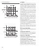
DB (Heating-Cooling Dead Band) Programming: The
adjustment of DB is dependent on the system requirements. If
a more positive value of DB (greater dead band) is used, an
unwanted cooling action can be avoided but an excessive over-
shoot over the set point will occur. If a more negative value of
DB (greater overlap) is used, an excessive overshoot over the
set point can be minimized, but an unwanted cooling action will
occur. It is adjustable in the range -36.0% to 36.0% of PB. A
negative DB value shows an overlap area over which both out-
puts are active. A positive DB value shows a dead band area
over which neither output is active.
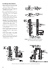
Output 2 ON-OFF control (alarm function): Output 2 can
also be configured with an alarm function. There are four kinds
of alarm functions that can be selected for output 2. These are:
DE.HI (deviation high alarm), DE.LO (deviation low alarm),
PV.HI (process high alarm), and PV.LO (process low alarm).
Refer to figure 3.3 and figure 3.4 for descriptions of the devia-
tion alarm and the process alarm.