
Instruction manual


12
Chapter 3 Programming
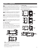
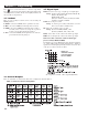
Press for 5 seconds and release to enter the setup menu.
Press to select the desired parameter. The upper display indi-
cates the parameter symbol, and the lower display indicates the
s
elected value of the parameter.
3–1 Lockout
There are four security levels that can be selected using the
LOCK parameter.
If NONE is selected for LOCK, then no parameter is locked.
If SET is selected for LOCK, then all setup data are locked.
If USER is selected for LOCK, then all setup data as well as
user data (refer to section 1-5) except the set point are
locked to prevent them from being changed.
If ALL is selected for LOCK, then all parameters are locked to
prevent them from being changed.
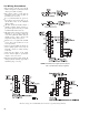
3–2 Signal Input
I
NPT: Selects the sensor type or signal type for signal input.
Range: (thermocouple) J-TC, K-TC, T-TC, E-TC, B-TC,
R
-TC, S-TC, N-TC, L-TC
(RTD) PT.DN, PT.JS
(Linear) 4–20mA, 0–20mA, 0–60mV, 0–1VDC,
0–5VDC, 1–5VDC, 0–10VDC
UNIT: Selects the process unit
Range: °C, °F, PU (process unit). If the unit is set for nei-
ther °C nor °F, then it defaults to PU.
DP: Selects the resolution of process value.
Range: (For T/C and RTD) NO.DP, 1-DP
(For linear) NO.DP, 1-DP, 2-DP, 3-DP
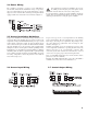
INLO: Selects the low scale value for the linear type input.
INHI: Selects the high scale value for the linear type input.
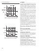
How to use the conversion curve for linear type
process values, INLO and INHI;
If 4–20mA is selected for INPT, SL specifies the input signal low
(i.e., 4mA), SH specifies the input signal high (i.e., 20mA), S
specifies the current input signal value, and the conversion curve
of the process value is shown as follows:
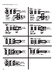
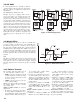
3–3 Control Outputs
There are four kinds of control modes that can be configured as shown in table 3.1.
SL = Setpoint Low Limit SH = Setpoint High Limit
Table 3.1 Heat-Cool Control Setup Value
Figure 3.1
Conversion Curve
for Linear Type
Process Value