
Instruction manual


9
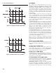
Proper sensor installation can eliminate many problems in a con-
trol system. The probe should be placed so that it can detect any
temperature change with minimal thermal lag. In a process that
requires fairly constant heat output, the probe should be placed
close to the heater. In a process where the heat demand is variable,
the probe should be close to the work area. Some experimentation
with probe location is often required to find the optimum position.
In a liquid process, the addition of agitation will help to eliminate
thermal lag. Since the thermocouple is basically a point measuring
device, placing more than one thermocouple in parallel can provide
an average temperature readout and produce better results in
most air heated processes.
Proper sensor type is also a very important factor in obtaining
precise measurements. The sensor must have the correct temper-
ature range to meet the process requirements. In special processes,
the sensor might have requirements such as leak-proof, anti-
vibration, antiseptic, etc.
Standard sensor limits of error are ±4°F (±2°C) or 0.75% of the
sensed temperature (half that for special) plus drift caused by
improper protection or an over-temperature occurrence. This
error is far greater than controller error and cannot be corrected
on the sensor except by proper selection and replacement.
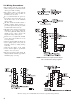
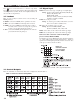
Note: A 2-wire RTD temperature sensor can be used if a short is
placed across the “B” terminals.
Example: For a TEC-9100 Controller, connect the 2-wire RTD to
terminals 4 & 5, and a short across terminals 5 & 6.
T
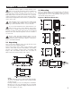
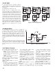
he controller is designed to operate at 11–26 VAC/VDC or
90–250 VAC. Check that the installation voltage corresponds to
the power rating indicated on the product label before connect-
ing power to the controller. The controller power input should be
equipped with a fuse and switch as shown below in figure 2.7
This equipment is designed for installation in an enclo-
s
ure which provides adequate protection against electric
shock. The enclosure must be connected to earth ground.
Local requirements regarding electrical installation should be
rigidly observed. Consideration should be given to prevent unau-
thorized personnel from accessing the power terminals.
2–4 Power Wiring
2–5 Sensor Installation Guidelines
2–6 Sensor Input Wiring
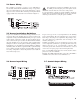
2–7 Control Output Wiring
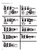
Control Output Wiring, continued…