
User`s manual


Connect Tech Xtreme/104-Plus User’s Manual
Revision 0.04
21
Electrical Interfaces (RS-232/422/485/TTL models)
RS-232/TTL Electrical Interface
The following control signals are available to ports configured for RS-232 and TTL mode: TxD,
RxD, RTS, CTS, RI, DTR, DSR, DCD, SG (Signal Ground) and +5V. See Figure 3 for the
location of Px1 RS-232/TTL port headers. See Figure 12 for information on configuring ports
for RS-232 or TTL mode. (Note: Current draw on +5V pins of all ports must not exceed 1 Amp.)
RS-422/485 Electrical Interface
In this mode, the port will communicate in RS-422 and RS-485 full duplex using the vertical
Px2 headers. (See Figure 3 for the location of Px2 headers). The following control signals are
available: TxD
+/
, RxD
+/
and SR (Signal Return). See Figure 12 for information on configuring
ports for RS-422/485 mode.
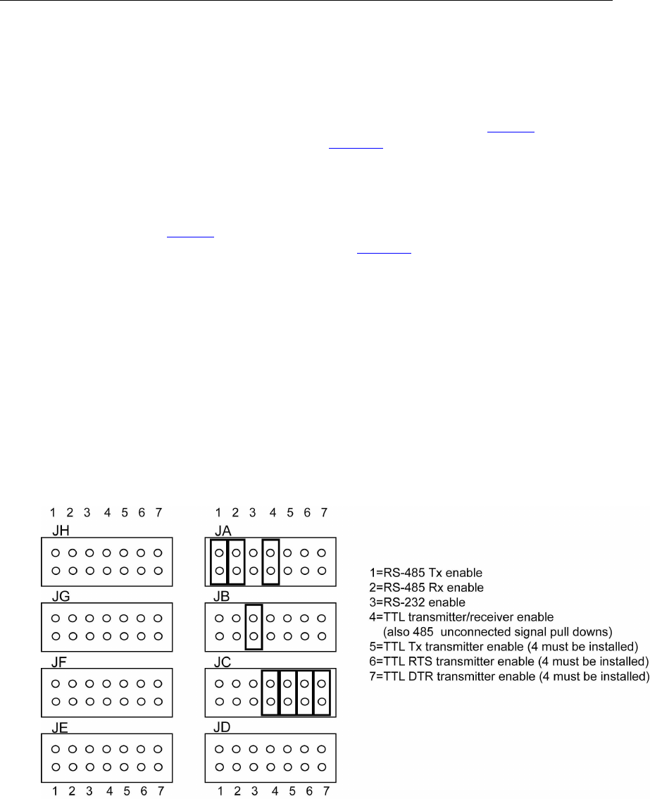
Jumper Block Settings
The following jumper blocks correspond to the following ports:
JA = Port 1 JE = Port 5
JB = Port 2 JF = Port 6
JC = Port 3 JG = Port 7
JD = Port 4 JH = Port 8
The pin functions are outlined in the following diagram:
Figure 12: Examples of various jumper block settings for RS-232/422/485/TTL models