
User`s manual


Connect Tech Xtreme/104-Plus User’s Manual
Revision 0.04
20
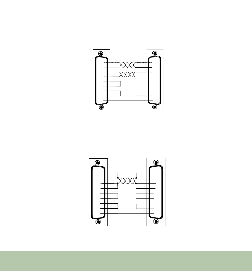
RS-422/485 Wiring Examples
Figure 10: RS-422/485 Wiring Diagram (4 wire)
Figure 11: RS-422/485 Wiring Diagram (2 wire)
Notes:
The RS-422/485 electrical interface consists of a differential signaling scheme. You should
always connect the signals with twisted pairs. Signal reference must be connected.
RTS +
RTS
-
CTS +
CTS
-
TxD +
TxD
-
RxD +
RxD
-
RxD +
TxD +
RxD
-
TxD -
RTS -
CTS -
RTS +
CTS +
SR
SR
Xtreme/104
-
Plus
and
Xtreme/104-Plus Opto adapter
RS-485/422 peripheral
3
4
2
5
6
9
7
8
1
RTS +
RTS
-
CTS +
CTS
-
TxD +
TxD -
RxD +
RxD
-
RxD +
TxD +
RxD
-
TxD
-
RTS
-
CTS
-
RTS +
CTS +
SR
SR
RS-485/422 peripheral
3
1
4
2
5
6
9
7
8
Xtreme/104
-
Plus
and
reme/104
-Plus Opto adapter