
User`s manual


Connect Tech Xtreme/104-Plus User’s Manual
Revision 0.04
18
Notes:
[1] When CAB8104 cable assembly is attached.
[2] 47Ω to GND. Ground is connected to the DC ground by a 47Ω resistor to
reduce ground loop current
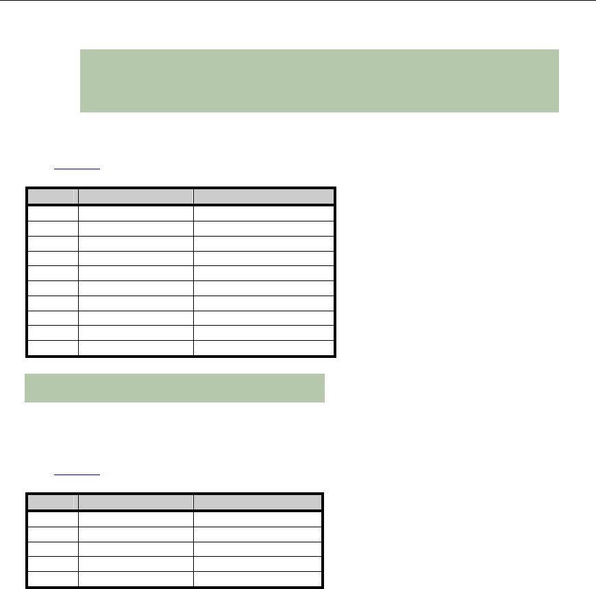
Table 5: RS-232/TTL Px1 right angled header pinouts (CAB104 compatible)
(See Figure 3 for Port numbering and locations)
Pin # RS-232/TTL signal Direction
1 DCD Input
2 DSR Input
3 RxD Input
4 RTS Output
5 TxD Output
6 CTS Input
7 DTR Output
8 RI Input
9 SG Signal Ground
10 +5V supply to external devices
Note: Total current draw on +5V pins of all ports must
not exceed 1A.
Table 6: RS-485 Px2 vertical header pinouts
(See Figure 3 for Port header numbering and locations)
Pin # RS-485 signal Direction
1 TxD+ Output
2 TxD- Output
3 RxD+ Input
4 RxD- Input
5 SR Signal Reference