
User`s manual


Connect Tech Xtreme/104-Plus User’s Manual
Revision 0.04
16
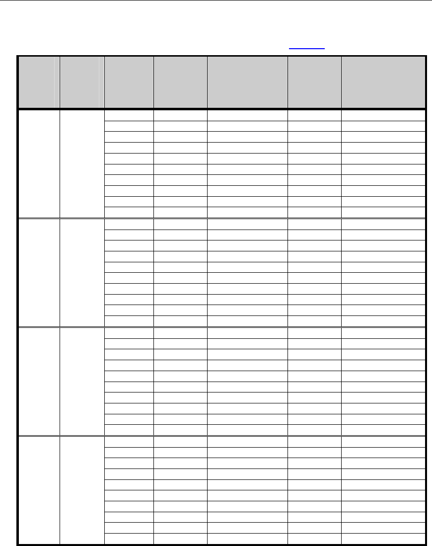
Table 2: I/O Signal Assignments for RS-232/422/485 Models (see Figure 1 for Port Numbering)
Header
Port No.
(4 port
models)
Header
Port No.
(8 port
models)
Pin No.
RS-232 Direction RS-
422/485
Direction
1 DCD Input RxD+ Input
2 DSR Input CTS- Input
3 RxD Input RxD- Input
4 RTS Output RTS+ Output
5 TxD Output TxD+ Output
6 CTS Input CTS+ Input
7 DTR Output TxD- Output
8 RI Input RTS- Output
9 SG Signal Ground SR Signal Reference
1 1 or 2
10 N/C No Connection N/C No Connection
11 DCD Input RxD+ Input
12 DSR Input CTS- Input
13 RxD Input RxD- Input
14 RTS Output RTS+ Output
15 TxD Output TxD+ Output
16 CTS Input CTS+ Input
17 DTR Output TxD- Output
18 RI Input RTS- Output
19 SG Signal Ground SR Signal Reference
2 3 or 4
20 N/C No Connection N/C No Connection
21 DCD Input RxD+ Input
22 DSR Input CTS- Input
23 RxD Input RxD- Input
24 RTS Output RTS+ Output
25 TxD Output TxD+ Output
26 CTS Input CTS+ Input
27 DTR Output TxD- Output
28 RI Input RTS- Output
29 SG Signal Ground SR Signal Reference
3 5 or 6
30 N/C No Connection N/C No Connection
31 DCD Input RxD+ Input
32 DSR Input CTS- Input
33 RxD Input RxD- Input
34 RTS Output RTS+ Output
35 TxD Output TxD+ Output
36 CTS Input CTS+ Input
37 DTR Output TxD- Output
38 RI Input RTS- Output
39 SG Signal Ground SR Signal Reference
4 7 or 8
40 N/C No Connection N/C No Connection