
User`s manual


Connect Tech Xtreme/104-Plus User’s Manual
Revision 0.04
15
Connectors/Pinouts
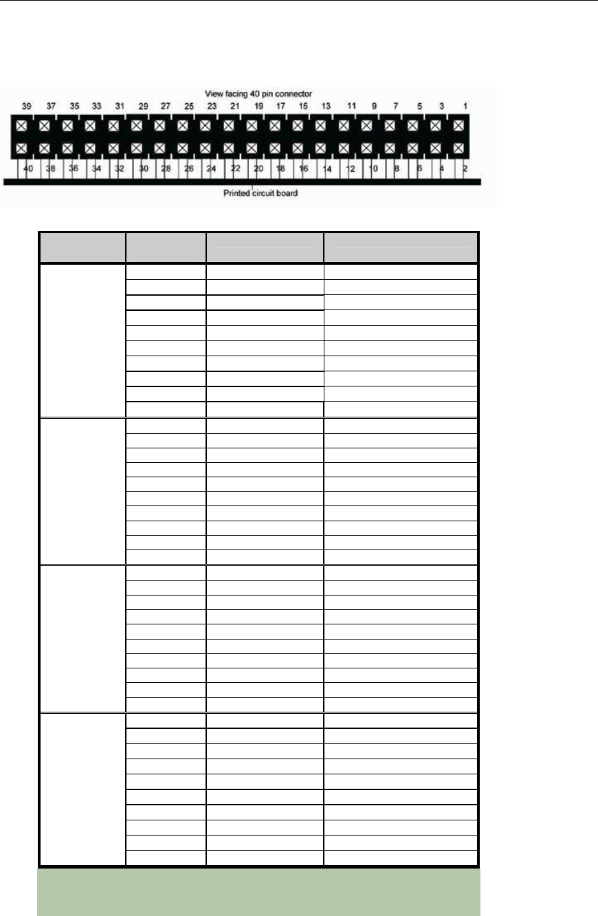
Figure 8: 40 pin connector: Pin numbering
Table 1
: I/O Signal Assignments for RS-423 models
Header
Port Number
Header
Pin Number
RS-423 Direction
1
RxD+ Input
2
CTS- Input
3
RxD- Input
4
RTSRef (RTS+) Signal Reference
5
TxDRef (TxD+) Signal Reference
6
CTS+ Input
7
TxD- Output
8
RTS- Output
9
GND Ground [1]
1
10
N/C No connection
11
RxD+ Input
12
CTS- Input
13
RxD- Input
14
RTSRef (RTS+) Signal Reference
15
TxDRef (TxD+) Signal Reference
16
CTS+ Input
17
TxD- Output
18
RTS- Output
19
GND Ground [1]
2
20
N/C No connection
21
RxD+ Input
22
CTS- Input
23
RxD- Input
24
RTSRef (RTS+) Signal Reference
25
TxDRef (TxD+) Signal Reference
26
CTS+ Input
27
TxD- Output
28
RTS- Output
29
GND Ground [1]
3
30
N/C No connection
31
RxD+ Input
32
CTS- Input
33
RxD- Input
34
RTSRef (RTS+) Signal Reference
35
TxDRef (TxD+) Signal Reference
36
CTS+ Input
37
TxD- Output
38
RTS- Output
39
GND Ground [1]
4
40
N/C No connection
Note:
[1] 47Ω to GND. Ground is connected to the DC ground by a 47Ω
resistor to reduce ground loop current.