
User manual


Connect Tech Xtreme/104 Plus, PCI-104 and PCI/104 Express Family User Manual
Revision 0.11
41
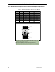
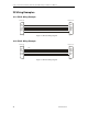
23.3 RS-422/485 Wiring Examples
Note: The RS-422/485 electrical interface consists of a differential signaling scheme.
You should always connect the signals with twisted pairs. The Signal Reference (GND)
must be connected.
TxD+
TxD-
GND
RxD+
RxD-
RxD+
RxD-
GND
TxD+
TxD-
Xtreme/104 RS485 Device
Figure 20: RS-422/485 Wiring Diagram (4 Wire)
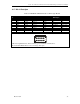
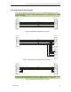
TxD+
TxD-
GND
RxD+
RxD-
RxD+
RxD-
GND
TxD+
TxD-
RxD+
RxD-
GND
TxD+
TxD-
Xtreme/104 RS485 Device 1
RS485 Device 2
Figure 21: RS-422/485 Wiring Diagram (4 Wire Multidrop)
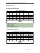
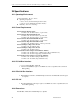
TxD+
TxD-
GND
RxD+
RxD-
RxD+
RxD-
GND
TxD+
TxD-
Xtreme/104 RS485 Device
Note: On the Xtreme/PCI-104 12 Port Opto the TxD+ to RxD+ and TxD- to RxD- wiring
is performed by the SP336 transceiver when Half Duplex mode is configured.
Figure 22: RS-422/485 Wiring Diagram (2 Wire)