
User manual


Connect Tech Xtreme/104 Plus, PCI-104 and PCI/104 Express Family User Manual
Revision 0.11
39
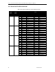
22.3 Xtreme/104 Plus RS232/485/TTL model
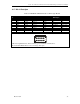
Table 8: RS-232/TTL Px1 Right Angled Header Pinouts (CAG104 Compatible)
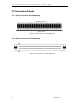
(See Figure 3 for port numbering and locations)
Pin #
RS-232/TTL Signal
Direction
1
DCD
Input
2
DSR
Input
3
RxD
Input
4
RTS
Output
5
TxD
Output
6
CTS
Input
7
DTR
Output
8
RI
Input
9
SG
Signal Ground
10
+5V
supply to external devices
Note: Total current drawn on +5V pins of all ports must
not exceed 1A.
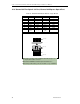
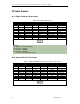
Table 9: RS-485 Px2 Vertical Header Pinouts
(See Figure 3 for port header numbering and locations)
Pin #
RS-485 Signal
Direction
1
TxD+
Output
2
TxD-
Output
3
RxD+
Input
4
RxD-
Input
5
SR
Signal Reference
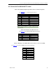
Table 10: Multipurpose I/O (MPIO) Header Pinout (Direct Connection to UART)
(See Figure 3 for location of MPIO header and pin numbering)
Pin #
Signal
1
MPIO1
2
MPIO2
3
MPIO3
4
MPIO4
5
MPIO5
6
MPIO6
7
MPIO7
8
MPIO8
9
GND
10
GND