
User manual

Connect Tech Xtreme/104-Plus, PCI-104 and PCI/104 Express Family User Manual
Revision 0.12
28
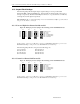
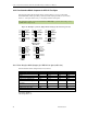
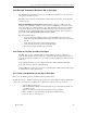
18.4 Line Interface Mode Jumpers for XIG 12 Port Opto
The following jumper block diagram depicts typical settings on a four-port selectable
Xtreme/PCI-104 12 Port Opto. Each port has two banks of jumper blocks, Jx.1y and Jx.2y.
Where ‘x’ is the port number and ‘y’ is the jumper number of that power.
Important Note!! Jumper removal and installation must only be performed when the power to
the XIG 12 Port Opto is off!
Figure 15: Examples of Various Jumper Block Settings for the 12 Port Opto model
J1.1A
J1.1B
J1.1C
J1.1D
J1.1E
J1.1F
Mode Bit 0
Slew
Mode Bit 3
Multidrop Enable
RXD B&T
RXD B&T
J1.2A
J1.2B
J2.1A
J2.1B
J2.1C
J2.1D
J2.1E
J2.1F
Mode Bit 0
Slew
Mode Bit 3
Multidrop Enable
RXD B&T
RXD B&T
TXD/RXD B&T
TXD/RXD B&T
TXD/RXD B&T
TXD/RXD B&T
J2.2A
J2.2B
J3.1A
J3.1B
J3.1C
J3.1D
J3.1E
J3.1F
Mode Bit 0
Slew
Mode Bit 3
Multidrop Enable
RXD B&T
RXD B&T
TXD/RXD B&T
TXD/RXD B&T
J3.2A
J3.2B
J4.1A
J4.1B
J4.1C
J4.1D
J4.1E
J4.1F
Mode Bit 0
Slew
Mode Bit 3
Multidrop Enable
RXD B&T
RXD B&T
TXD/RXD B&T
TXD/RXD B&T
J4.2A
J4.2B
J6.1A
J6.1B
J6.1C
J6.1D
J6.1E
J6.1F
Mode Bit 0
Slew
Mode Bit 3
Multidrop Enable
RXD B&T
RXD B&T
TXD/RXD B&T
TXD/RXD B&T
J6.2A
J6.2B
RS232 RS485 Full
Duplex 4-wire
Slow Slew
RS485
2-Wire
RS485 Multidrop
4-wire
Loopback
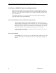
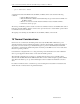
18.4.1 Line Interface Mode Jumpers for XIG 12 Port Opto (table view)
The Line Interface Mode Jumpers function is as follows:
Mode / Jumpers
Jx..1A
Jx..1B
Jx..1C
Jx..1D
Local Loopback
IN
Don’t Care
IN
OUT
RS232
IN
OUT
OUT
OUT
RS232 slow slew
IN
IN
OUT
OUT
RS485 4-wire Full Duplex
OUT
OUT
OUT
OUT
RS485 4-wire Full Duplex
slow slew
OUT
IN
OUT
OUT
RS485 4-wire Multidrop
OUT
OUT
OUT
IN
RS485 2-wire
OUT
OUT
IN
IN
RS485 2-wire slow slew
OUT
IN
IN
IN
DO NOT USE ANY OTHER COMBINATIONS THAN THE ABOVE
IN =Jumper Installed
Out=Jumper Removed