
User manual

Connect Tech Xtreme/104 Plus, PCI-104 and PCI/104 Express Family User Manual
Revision 0.11
25
17 Electrical Interfaces (RS-232/422/485/TTL Models)
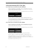
17.1 RS-232/TTL Electrical Interface
The following control signals are available to ports configured for RS-232 and TTL mode: TxD,
RxD, RTS, CTS, RI, DTR, DSR, DCD, SG (Signal Ground) and +5V. See Figure 3 for the
location of Px1 RS-232/TTL port headers. See Figure 13 for information on configuring ports
for RS-232 or TTL mode. (Note: Current draw on +5V pins of all ports must not exceed 1 Amp).
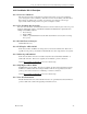
17.2 RS-422/485 Electrical Interface
In this mode, the port will communicate in RS-422 and RS-485 full duplex using the vertical
Px2 headers. (See Figure 3 for the location of Px2 headers). The following control signals are
available: TxD+/, RxD+/ and SR (Signal Reference). See Figure 13 for information on configuring
ports for RS-422/485 mode.
17.3 Jumper Block Settings
The following jumper blocks correspond to the following ports:
JA = Port 1 JE = Port 5
JB = Port 2 JF = Port 6
JC = Port 3 JG = Port 7
JD = Port 4 JH = Port 8
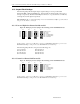
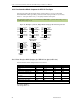
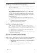
The pin functions are outlined in the following diagram:
Figure 14: Examples of Various Jumper Block Settings for RS-232/422/485/TTL Models
In the example in Figure 2, port 1 (JA) is configured for RS-422/485 full duplex, port 2 (JB) is
configured for RS-232, port 3 (JC) is configured for TTL, and ports 4 to 8 (JD to JH) are
disabled.
When all jumpers are removed, the corresponding ports are completely disabled. The UART will
receive no data from these ports, even if an external source is driving the headers.
Note: There are eight solder jumpers on the back of the board that correspond to the
vertical (Px2) headers on the front of the board. (See Figure 3 for location of Px2
headers). If necessary, you can ensure TxD+/- pins on specified vertical headers
remain active by shorting the appropriate jumper. This is possible even if the board is
not in RS-422/485 mode or it is disabled.