
User manual

Connect Tech Xtreme/104-Plus, PCI-104 and PCI/104 Express Family User Manual
Revision 0.12
22
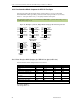
16.3 Jumper Block Settings
The following jumper block diagram depicts typical settings on a four-port selectable
Xtreme/104-Plus or Xtreme/104-Plus Opto. Jumper blocks JA, JB, JC and JD control ports 1
through 4, respectively. The Xtreme/104 Express can have 4 or 8 ports which are controlled by
J1 though J4, and J1 though J8 respectively.
Important Note!! We recommend that jumper removal and installation only be performed when
the power to the Xtreme card is off!
16.3.1 Four and Eight Port Xtreme/104 Plus models
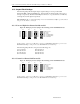
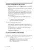
Figure 12: Example of Various Jumper Block Settings for RS-232/422/485 Models
In this example, port 1 is set to RS-232, port 2 is set to RS-422/485 half duplex, port 3 is set to
RS-422/485 full duplex, and port 4 is set to RS-422/485 4-wire multi-drop.
The following jumper blocks correspond to the following ports:
JA = J1 = Port 1 JE = J5 = Port 5
JB = J2 = Port 2 JF = J6 = Port 6
JC = J3 = Port 3 JG = J7 = Port 7
JD = J4 = Port 4 JH = J8 = Port 8
16.3.2 Sixteen Port Xtreme/104 Plus models
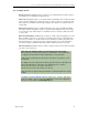
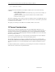
Figure 13: Example of Various Jumper Block Settings for RS-232/422/485 Models
In this example, port 1 is set to RS-232, port 2 is set to RS-422/485 half duplex, port 3 is set to
RS-422/485 full duplex, and port 4 is set to RS-422/485 4-wire multi-drop.
J1A
J1B
J1C
J1D
J1E
J1F
JA
J2A
J2A
J2A
J2A
J2A
J2A
JB5
JB
Port 1
Port 2
J3A
J3B
J3C
J3D
J3E
J3F
JC
Port 3
J4A
J4B
J4C
J4D
J4E
J4F
JD
Port 4
RS-485 selection
TxD control
RxD control
RxD Termination/Bias
RxD Termination/Bias
TxD Termination
JA0
JA1
JA2
JA3
JA4
JA5
JA
JB0
JB1
JB2
JB3
JB4
JB5
JB
Port 1
Port 2
JC0
JC1
JC2
JC3
JC4
JC5
JC
Port 3
JD0
JD1
JD2
JD3
JD4
JD5
JD
Port 4
RS-485 selection
TxD control
RxD control
RxD Termination/Bias
RxD Termination/Bias
TxD Termination