
User manual

Connect Tech Xtreme/104 Plus, PCI-104 and PCI/104 Express Family User Manual
Revision 0.11
19
15 Hardware Configuration
15.1 Safety note
To ensure the most reliable and safe operation, never install or remove jumpers or adjust the rotary
switch while the power is on!
15.2 Interrupts and Memory Address Selection
Xtreme/104 boards are PCI and PCI Express cards, so the host computer’s BIOS or Operating
System will automatically set interrupts and memory addresses when you reboot after
installation.
15.3 Xtreme/104 Plus and Xtreme/PCI-104 ID Selection
Up to four PC/104-Plus or PCI-104 boards can reside within a single PC/104 module stack. Each
card within the stack must have a unique ID ranging from zero to three.
(this section does not apply to PCIe/104 cards )
Depending on the model of your Xtreme/104-Plus adapter, you will
be required to set either a pair of jumpers or a rotary switch to
specify where your card is located within the stack. (Ensure that no
two boards share an ID number.)
In systems designed prior to the PC/104-Plus 2.0 specification, the fourth ID was reserved for
target only devices and did not support bus mastering. Since the Xtreme/104-Plus is not a bus
mastering device, we would recommend an assignment of ID 3. This leaves three of the IDs in
the PC/104-Plus stack available for bus mastering devices.
In systems designed post PC/104-Plus 2.0 specification, all four IDs support bus mastering, so
there is no advantage to setting the Xtreme/104-Plus ID to 3. Regardless of which PC/104-Plus
specification version the system is using, , the Xtreme/104-Plus will work with any ID selected
as long as no other device in the system is using the same ID.
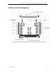
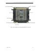
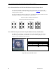
15.3.1 Xtreme/104 Plus ID Selection Using the Rotary Switch
If your Xtreme/104-Plus or Xtreme/104-Plus Opto is equipped with a rotary switch, turn the
knob on the switch so that the arrow points at the ID you would like to use. (See Figure 6 for the
location of the rotary switch on the board). Use the following settings to set your adapter’s
location (or ID) within the stack:
Figure 9: Rotary Switch ID Selection
Module Slot
Switch Position
1
0 or 4
2
1 or 5
3
2 or 6
4
3 or 7
CPU
0
1
2
3