
User`s guide
RS-485.................................................................................................... 16
APPENDIX D - ASYNCHRONOUS COMMUNICATIONS ...............17
APPENDIX E - SILK-SCREEN ....................................................19
APPENDIX F - COMPLIANCE NOTICES ...................................20
FEDERAL COMMUNICATIONS COMMISSION STATEMENT............ 20
EMC DIRECTIVE STATEMENT........................................................... 20
Figures
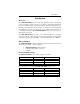
Figure 1 - Address Selection Table ....................................................................2
Figure 2 - DIP-Switch Illustration......................................................................2
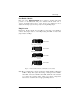
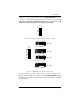
Figure 3 - Headers E1, E2, E3, and E4 (Factory Default).................................3
Figure 4 - Header E5, Normal IRQ Mode...........................................................4
Figure 5 - Header E5, Shared IRQ Mode ...........................................................4
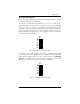
Figure 6 - Header E5, Sharing IRQs with another adapter............................5
Figure 7 - IRQ Headers E1 - E5 (Factory Default)...........................................5
Figure 8 - Headers E8 and E9 RS-485 Mode Enable........................................6
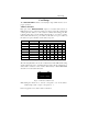
Figure 9 - Four Port RS-232/RS-422 Configuration Table...........................7
Figure 10 - Asynchronous Communications Bit Diagram ..........................17