
User`s guide

Technical Description
OMG-ISO-COMM Page 10
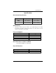
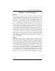
Connector Pin Assignments
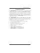
RS-422 (DB 9 Male)
Signal Name Pin # Mode
GND Ground 5
TX + Transmit Data Positive 4 Output
TX- Transmit Data Negative 3 Output
RTS+ Request To Send Positive 6 Output
RTS- Request To Send Negative 7 Output
RX+ Receive Data Positive 1 Input
RX- Receive Data Negative 2 Input
CTS+ Clear To Send Positive 9 Input
CTS- Clear To Send Negative 8 Input
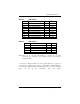
RS-232 (DB 9 Male)
Signal Name Pin # Mode
GND Ground 5
TD Transmit Data 3 Output
RTS Request To Send 7 Output
RD Receive Data 2 Input
CTS Clear To Send 8 Input
Note: These are the only pins that should be connected in your cable.
Connecting any other pins on the DB-9 connector could result in
intermittent data.
Technical Note: Please terminate any control signals that are not going to be
used. The most common way to do this is connect RTS to CTS and RI. Also,
connect DCD to DTR and DSR. Terminating these pins, if not used, will help
insure you get the best performance from your adapter.